You might have a point about the bias if there is insufficient bias, although I believe you can get non-polar tantalums as well.
Has anyone measured the bias voltage across these 47uF coupling caps to see if there is any ? If the originals are polarised aluminium electrolytics with no bias that's not great either.. and fitting the same would not be a good idea as they would also fail eventually. Whatever goes in should be non-polar if there is little or no bias.
I agree with bypassing it with a 0.1uF film cap - if I can physically squeeze it in. Electrolytics with no bypass directly in a signal path that can supposedly pass audio up to 96Khz is a big no-no, there's no way it will be flat up to those high frequencies without additional bypassing and I'm surprised nobody in this thread has addressed this when trying to perform mods to improve sound quality.
At the moment I don't have a working scope so I'm going to have to sort that out before I can properly look at this. Maybe I will go a bit further than just trying to fix the channel imbalance. At the moment my stereo setup can work fairly well without any EQ so I can pull the DEQ out of the system and pick away at it carefully.
Is there a consensus here that replacing the various mentioned signal path capacitors alone is enough to improve the quality significantly without trying to replace the (difficult to remove) opamps ?
Last edited:
For 10 years, I've been curious about the hunt for perfection in the DCX by mods to the analog sections. Lots of despair about super-sonic jitters but not much evidence of audible shortcomings or audible improvement. REW testing I've ever done of FR, noise, and THD seem extravagantly excellent to my perspective.
How many people are still using the analog input to the DCX or DEQ instead of AES-SPDIF/coax digital input? Or can't find $50 for an upstream ADC instead of this risky mod?
With 1% distortion in speakers on a good day, does .05% distortion - and only north of 10kHz - in the Behringers impair sound quality?
Having said that, I greatly admire the thought shown in this thread. But also the generosity of posters in sharing their knowledge and being helpful to others. Thanks.
B.
I've been happy with the sound quality of mine for years and have found the measurements to be pretty good overall, for me the issue is channel imbalance between the two channels that has developed as it has aged, as well as a shift in frequency response of one channel relative to the other. A small shift but it is quite audible.For 10 years, I've been curious about the hunt for perfection in the DCX by mods to the analog sections. Lots of despair about super-sonic jitters but not much evidence of audible shortcomings or audible improvement. REW testing I've ever done of FR, noise, and THD seem extravagantly excellent to my perspective.
I use only analogue inputs and outputs - the amplifier it is connected to is purely analogue.How many people are still using the analog input to the DCX or DEQ instead of AES-SPDIF/coax digital input? Or can't find $50 for an upstream ADC instead of this risky mod?
Depends what form that distortion is in. If it was .05% harmonic distortion then no you wouldn't hear it at all and yes speakers are far worse than that for harmonic distortion.With 1% distortion in speakers on a good day, does .05% distortion - and only north of 10kHz - in the Behringers impair sound quality?
However intermod distortion between high treble frequencies (which on their own might be inaudible to the listener) generating audible products in the midrange could certainly be heard with the right source material, and would sound a bit like aliasing - I think that's what the modifications earlier in this thread are trying to address, and I don't have a problem with that.
Not sure if I'm brave enough to attempt it though, I may just stick to fixing the channel imbalance and getting it back to factory original performance.
Last edited:
Now that I have a scope again I spent some time troubleshooting the I/O board and found the channel imbalance problem does indeed seem to be electrolytic coupling caps - specifically two of them in the right channel.
First I did some accurate gain comparisons between left and right channels and the relay bypass. As expected the relay bypass is a perfect gain match, so the figures below are relative to the relay bypass:
+12dBu mode
40hz
Left: -0.46dB
Right: -3.07dB
1Khz
Left: -0.36dB
Right: -2.06dB
10Khz
Left: -0.43dB
Right: -1.70dB
So yeah, 2.6dB down on the right channel at 40hz vs left, not good...
While there was a fraction of a dB difference in overall level in +22dBu mode the trends were all the same.
Next I wanted to find out how much of that loss was input stage vs output stage, so I used the width processor set to minimum width which effectively turns the signal path into mono mode.
I was then able to feed the test signal into only the left input and compare left and right outputs. (I also tried it feeding only into the right input - same result)
In this mode the channels matched each other within 0.05dB so that confirmed all the channel imbalance is on the input side and the output is perfectly OK. This tallies with the VU meters to be honest because the VU meters show an imbalance on the input signal as well.
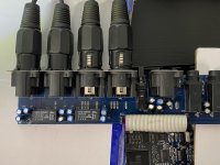
I started tracing the circuit from the input connectors referring to the DCX2496 schematic posted earlier in the thread unfortunately there are large differences in the input stage between my DEQ2496 and the circuit given earlier, for example it turns out both signal + and - from the XLR connector go directly to two 47uF coupling capacitors while none are shown in the circuit above...
And funnily enough the coupling capacitor on the positive input of the right channel is the main fault, with a loss of about 2dB across it at 40hz - when I bypass this with a 10uF polypropylene cap I have lying around the level goes up by about 1.8dB, so given this is 1/4 of the correct value of the original cap and it still makes this much difference the electrolytic must either be down to less than 1/10th of its correct value or have a really high ESR... either way it's stuffed.
There is a second 47uF next to it that is also faulty although the loss here is less - around 0.5dB, and bridging it with the 10uF cap still makes a significant difference. So also faulty.
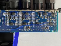
On the picture below C19 is the one that is really bad and C18 is the not so bad but still faulty cap:

Bridging the 10uF across the same caps in the left channel (or indeed any other caps) makes zero difference, so it seems I only have two faulty caps. I will of course replace all of these 47uF caps, even the ones on the phone jack outputs I don't use...
The next question is what to replace them with - I've been swayed away from tantalum but I'm thinking that if I can find some that will physically fit I really ought to replace them with non-polar electrolytics ?
Of the 15 or so 47uF caps more than half of them, including both faulty ones, are operating with zero DC bias. This is obviously not ideal for a polarised electrolytic, especially one going to the input socket.
A few have 2.8v across them and a couple 14.88 across them. Are there any drawbacks to simply replacing all of the 47uF 25v (and the one 10uF) with non-polar electrolytics ?
These ones are 12mm tall by 5mm diameter but there is plenty more height available and they could probably fit 6mm diameter without too much trouble. I haven't yet looked to see what's available.
I'm also considering bypassing the ones being used for coupling with 0.1uF, but what would be good to use but is still small enough to fit under the board and be good for audio ? Polypropylene ?
I've also noticed a bodge wire on my board - while I did replace the relays on mine and had some difficulty with the PCB I have no recollection of having to bypass a faulty trace - does anyone else's board have this blue wire ??

The foam pads on the bottom have completely rotted and gone hard and crumbly, so I've got a bit of board clean up to do and new foam spacers to fit before it goes back together...
First I did some accurate gain comparisons between left and right channels and the relay bypass. As expected the relay bypass is a perfect gain match, so the figures below are relative to the relay bypass:
+12dBu mode
40hz
Left: -0.46dB
Right: -3.07dB
1Khz
Left: -0.36dB
Right: -2.06dB
10Khz
Left: -0.43dB
Right: -1.70dB
So yeah, 2.6dB down on the right channel at 40hz vs left, not good...
While there was a fraction of a dB difference in overall level in +22dBu mode the trends were all the same.
Next I wanted to find out how much of that loss was input stage vs output stage, so I used the width processor set to minimum width which effectively turns the signal path into mono mode.
I was then able to feed the test signal into only the left input and compare left and right outputs. (I also tried it feeding only into the right input - same result)
In this mode the channels matched each other within 0.05dB so that confirmed all the channel imbalance is on the input side and the output is perfectly OK. This tallies with the VU meters to be honest because the VU meters show an imbalance on the input signal as well.
I started tracing the circuit from the input connectors referring to the DCX2496 schematic posted earlier in the thread unfortunately there are large differences in the input stage between my DEQ2496 and the circuit given earlier, for example it turns out both signal + and - from the XLR connector go directly to two 47uF coupling capacitors while none are shown in the circuit above...
And funnily enough the coupling capacitor on the positive input of the right channel is the main fault, with a loss of about 2dB across it at 40hz - when I bypass this with a 10uF polypropylene cap I have lying around the level goes up by about 1.8dB, so given this is 1/4 of the correct value of the original cap and it still makes this much difference the electrolytic must either be down to less than 1/10th of its correct value or have a really high ESR... either way it's stuffed.
There is a second 47uF next to it that is also faulty although the loss here is less - around 0.5dB, and bridging it with the 10uF cap still makes a significant difference. So also faulty.
On the picture below C19 is the one that is really bad and C18 is the not so bad but still faulty cap:
Bridging the 10uF across the same caps in the left channel (or indeed any other caps) makes zero difference, so it seems I only have two faulty caps. I will of course replace all of these 47uF caps, even the ones on the phone jack outputs I don't use...
The next question is what to replace them with - I've been swayed away from tantalum but I'm thinking that if I can find some that will physically fit I really ought to replace them with non-polar electrolytics ?
Of the 15 or so 47uF caps more than half of them, including both faulty ones, are operating with zero DC bias. This is obviously not ideal for a polarised electrolytic, especially one going to the input socket.
A few have 2.8v across them and a couple 14.88 across them. Are there any drawbacks to simply replacing all of the 47uF 25v (and the one 10uF) with non-polar electrolytics ?
These ones are 12mm tall by 5mm diameter but there is plenty more height available and they could probably fit 6mm diameter without too much trouble. I haven't yet looked to see what's available.
I'm also considering bypassing the ones being used for coupling with 0.1uF, but what would be good to use but is still small enough to fit under the board and be good for audio ? Polypropylene ?
I've also noticed a bodge wire on my board - while I did replace the relays on mine and had some difficulty with the PCB I have no recollection of having to bypass a faulty trace - does anyone else's board have this blue wire ??
The foam pads on the bottom have completely rotted and gone hard and crumbly, so I've got a bit of board clean up to do and new foam spacers to fit before it goes back together...
Attachments
Last edited:
Ok never mind, I can't find any non-polar electrolytics in that value/size range from any of the suppliers I use so I guess I'll just have to get decent quality polar types!
I am planning to bypass the ones directly in the signal path with 0.1uF metalized polyester film types as well though if I can fit them under the board, and I'll do some sweeps to see if this does affect the high frequency response in any noticeable way.
I am planning to bypass the ones directly in the signal path with 0.1uF metalized polyester film types as well though if I can fit them under the board, and I'll do some sweeps to see if this does affect the high frequency response in any noticeable way.
Last edited:
Your left channel seems to be about 2 dB louder (readily addressed by gain management somewhere) and there is an inaudible variation with frequency about plus and minus .7 dB between channels.
Not something I'd lose sleep over, or want to warm up my soldering iron and get my magnifying glass, even if I could reliably measure it.
B.
Not something I'd lose sleep over, or want to warm up my soldering iron and get my magnifying glass, even if I could reliably measure it.
B.
Last edited:
Each to their own of course, but for me a stereo gain imbalance of 2dB is considerable, pulling the stereo image quite a long way off centre and subjectively also giving the impression of "compressing" the perceived stereo width more towards mono.Your left channel seems to be about 2 dB louder (readily addressed by gain management somewhere) and there is an inaudible variation with frequency about plus and minus .7 dB between channels.
Not something I'd lose sleep over, or want to warm up my soldering iron and get my magnifying glass, even if I could reliably measure it.
B.
I noticed the subjective effects of the problem long before I ever took any measurements - I only took the channel balance measurements because I noticed a fairly obvious problem in normal music playback, not the other way around.
And a 1.7dB up tilt from bass to treble in the right channel is also very obvious and noticeable and certainly explains why the speakers are sounding a little thinner than they should lately.
While I have a workaround in place to balance the levels and frequency response of the two channels to some degree, it's quite inconvenient and not entirely accurate as I've had to put the DEQ2496 in stereo EQ mode where you can adjust the EQ of left and right channels independently, (normally one set of EQ adjustments is shared and mirrored between both channels in "Dual Mono" mode) but this is a PITA when trying to make any adjustments especially if the EQ on both channels has to be set differently to get the same result.
In short, I want it fixed, and there's no way I would leave nearly dead coupling capacitors in place now I know what the problem is and how easily it can be fixed.
The capacitors are on order and will be fitted as soon as they arrive...
All fixed, some 16 capacitors later.
While I identified two caps that were specifically relating to the right channel fault during my initial testing it turns out after measuring them all during removal that of the 16 47uF caps on that board 4 were completely open circuit so I'm not sure how it was even working, although some were in other functions like the RTA input which I haven't used in over a decade...
C19 which made the most difference to the right channel level was down from 47uF to just 0.2uF C18 was down to 10uF.
The values were all over the place at random - some just a few uF or completely dead, some nearly at their full value. I suspect the ones that were still relatively good were ones that have bias voltage although I didn't actually check that to confirm it. There were two different batches of capacitors fitted from the factory - one lot blue, one lot black.
I replaced them with good quality Panasonic types so hopefully they will last longer, and will probably see out the rest of the useful life of the device considering it's now 17 years old.
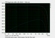
Here are the before and after measurements. Note that the vertical scale is blown up a lot to measure the differences accurately making the high frequency roll off appear worse than it really is.
Before:
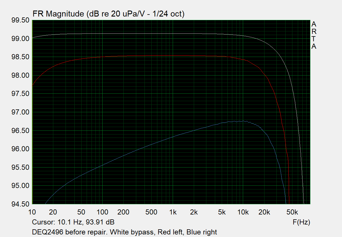
The upwards slope on the right channel is really obvious, at 30Hz the difference is 3.3dB, at 10Khz it is about 1.8dB.
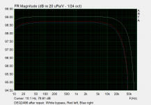
After:
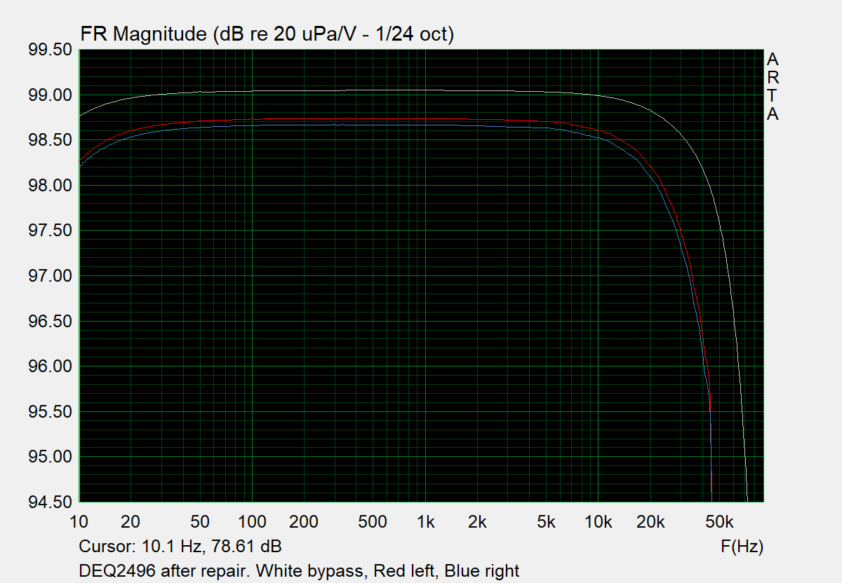
Channel matching is near on perfect now with the two channels within 0.06dB up to a few Khz and about 0.1dB at 20Khz.
Also of note is that even the "good" left channel has increased in level about 0.3dB and has significantly less bass roll off, so lower capacitance values were still affecting the left channel somewhat.
Although I did order a bag of 0.1uF polyester film caps to bypass the electrolytics, in the end after looking at the measurements and doing some reactance calculations I opted not to install them.
So I'm very happy with this fix - at the age these are getting to I suggest people measure theirs as well because it's likely some of the zero bias coupling caps in the input/output circuits have dried out and are compromising the performance. I was shocked at how many had outright failed let alone dropped to extremely low values.
While I identified two caps that were specifically relating to the right channel fault during my initial testing it turns out after measuring them all during removal that of the 16 47uF caps on that board 4 were completely open circuit
so I'm not sure how it was even working, although some were in other functions like the RTA input which I haven't used in over a decade...C19 which made the most difference to the right channel level was down from 47uF to just 0.2uF
C18 was down to 10uF.The values were all over the place at random - some just a few uF or completely dead, some nearly at their full value. I suspect the ones that were still relatively good were ones that have bias voltage although I didn't actually check that to confirm it. There were two different batches of capacitors fitted from the factory - one lot blue, one lot black.
I replaced them with good quality Panasonic types so hopefully they will last longer, and will probably see out the rest of the useful life of the device considering it's now 17 years old.
Here are the before and after measurements. Note that the vertical scale is blown up a lot to measure the differences accurately making the high frequency roll off appear worse than it really is.
Before:
The upwards slope on the right channel is really obvious, at 30Hz the difference is 3.3dB, at 10Khz it is about 1.8dB.
After:
Channel matching is near on perfect now with the two channels within 0.06dB up to a few Khz and about 0.1dB at 20Khz.
Also of note is that even the "good" left channel has increased in level about 0.3dB and has significantly less bass roll off, so lower capacitance values were still affecting the left channel somewhat.
Although I did order a bag of 0.1uF polyester film caps to bypass the electrolytics, in the end after looking at the measurements and doing some reactance calculations I opted not to install them.
So I'm very happy with this fix - at the age these are getting to I suggest people measure theirs as well because it's likely some of the zero bias coupling caps in the input/output circuits have dried out and are compromising the performance. I was shocked at how many had outright failed let alone dropped to extremely low values.
Attachments
Last edited:
Sure, these are the ones I used:Hi, you did a great job! Which capacitors did you fit exactly? I mean part number / make / model / specifications. Thanks
47uF 25v:
Panasonic Electrolytic Capacitor, 47 µF, 25 V, EB Series, ± 20%, Radial Leaded, 5000 hours @ 105°C - EEUEB1E470S
https://cpc.farnell.com/webapp/wcs/...ic&partNumber=CA08312&storeId=10180&langId=69
10uF 50v:
Panasonic Electrolytic Capacitor, 10 µF, 50 V, EB Series, ± 20%, Radial Leaded, 5000 hours @ 105°C - EEUEB1H100S
https://cpc.farnell.com/panasonic/eeueb1h100s/capacitor-10uf-50v-5x11mm/dp/CA08331
Both are rated at 5000 hours at 105C while the originals were only rated for an unknown number of hours at 85C, so they are higher temperature rated.
My unit runs quite hot because it's in an enclosed cabinet running 24/7 with other equipment sitting on top, so it's possible heat has been a factor.
There are 15x 47uF caps and 1x 10uF and because these are multiples of 10 only I ended up ordering 30 of the 47uF and 10 of the 10uF, but it's still pennies.
Because I had quite a few extras I was able to do my own bin sorting to find 15 that were all very close to 47uF. (There were a few outliers reaching out to 44 and 49uF)
They're a perfect size match to the originals. Keep in mind that my unit is an original revision 1.x unit (one of the very first in fact) so later revisions may not have the exact same capacitors in the I/O board, but I'm sure suitable capacitors could be found from the same Panasonic EB series.
Last edited:
Bought 2003 or 2004. If I remember right it was within a year of release.Thanks for very nice presentation of data and good write-up.
How old is your device?
Can't find my original purchase receipt as I don't have access to the email address that I used back then any more.
I ordered it all the way from B&H Photo in the USA to New Zealand as it was the only seller I could find with a decent price who would ship all the way to NZ...
Thanks.
Running a "value priced" device 24/7 in an under-ventilated space for 18 years does provide a benchmark for aging of electrolytic caps resulting in plus and minus .7dB loss.
Your parts resources are in great shape to have 16 caps on hand for replacement and a magnifying glass and leisure time too. Others may find buying a new DSP a better move to correct the plus and minus .7dB failure.
BTW, it occurs to me that since your DSP is a crossover, the freq error really has to be looked at band by band, not a loss from top to bottom. And any gain differences can be readily managed by the input attenuators on the 6 amps.
So actually, viewed in three bands, the failure is more like plus and minus .2 dB within each of three bands. That would be astonishingly wonderful by the standards of many other audiophiles* before the cap replacement.
B.
* and monumentally better than the results at your chair on the best of days
Last edited:
For the last 3 years it has been in a closed cabinet that does does have a partially open back where cables come in but there is also a lot of other equipment in the cabinet generating heat including an Xbox Series X, Tivo, stereo amp etc...so the inside of the cabinet is around 30C when things are turned on. However prior to this it spent most of its life sitting out in the open.Thanks.
Running a "value priced" device 24/7 in an under-ventilated space for 18 years does provide a benchmark for aging of electrolytic caps resulting in plus and minus .7dB loss.
Not sure where you're getting +/- 0.7dB from, the loss at low frequencies in the bad channel was well over 3dB as shown in my graphs.
I didn't have them on hand - I ordered them in specifically for the repair - see the post prior to the one with the graphs in it where I said I was ordering them.Your parts resources are in great shape to have 16 caps on hand for replacement and a magnifying glass and leisure time too. Others may find buying a new DSP a better move to correct the plus and minus .7dB failure.
If you can suggest another DSP with the same functionality as the DEQ2496 that doesn't cost the earth I'm listening. I've had a quick look and there doesn't seem to be anything even 17 years later...
There are things like the MiniDSP which doesn't have its own UI and is designed to be programmed from a PC and then left alone. There are a lot of "room equaliser" units that are basically only designed for subwoofer integration so are only designed to adjust low frequencies - and these are usually 2x to 5x the price of a new DEQ2496 and do far, far less...
I could buy a second hand DEQ2496 on ebay - there are quite a few there for around £100, but it's very likely that they have the same dried out capacitor problem if they are older so I'd be back to replacing caps anyway. And they may have other problems mine doesn't.
Sometimes it's better to stick with the devil you know and just repair it. As a general rule I'm a repair stuff not throw it out and replace it at the first sign of trouble kinda guy.
You're confusing it with the DCX2496. The DCX2496 is a 3 band digital crossover, (having 6 channels) the DEQ2496 is not a crossover at all, it's "only" a stereo signal processor, which does graphic equaliser, parametric equaliser, compressor, stereo width enhancement among many other things... so there are only two channels to measure.BTW, it occurs to me that since your DSP is a crossover, the freq error really has to be looked at band by band, not a loss from top to bottom. And any gain differences can be readily managed by the input attenuators on the 6 amps.
So actually, viewed in three bands, the failure is more like plus and minus .2 dB within each of three bands. That would be astonishingly wonderful by the standards of many other audiophiles* before the cap replacement.
Last edited:
"You're confusing it with the DCX2496... the DEQ2496 is not a crossover at all, it's "only" a stereo signal processor, which does graphic equaliser, parametric equaliser, compressor, stereo width enhancement among many other things... so there are only two channels to measure."
Oops.
But on the other hand, why go to all that bother when you can merely raise the low frequencies by less than a dB (which most of us couldn't possibly hear) and lower the upper frequencies by less than a dB (which most of us couldn't possibly hear).
B.
Oops.
But on the other hand, why go to all that bother when you can merely raise the low frequencies by less than a dB (which most of us couldn't possibly hear) and lower the upper frequencies by less than a dB (which most of us couldn't possibly hear).
B.
Given that one of the main input coupling capacitors was found to be nearly dead and progressively failing over the last year or so, arguing against repairing it is kind of silly, it was a fault that needed repairing before it died completely, and the degree of attenuation/shift in frequency response has been getting worse over time. (I've noticed it getting worse which is why I've finally got around to doing something about it)But on the other hand, why go to all that bother when you can merely raise the low frequencies by less than a dB (which most of us couldn't possibly hear) and lower the upper frequencies by less than a dB (which most of us couldn't possibly hear).
It's not possible to compensate that slope correctly anyway even if it remained stable as the minimum step size for the graphic EQ and parametric EQ settings is 0.5dB, and there is no continuous slope function like a linear equaliser. The nearest is a 6dB/oct shelf function and it does a poor job trying to compensate a continuous slope - that is what I was previously using as a work around.
From reading a lot of your other responses to posts over time its clear that you're happy to accept a lot worse response errors that many other people are, and frequently wave it away with "well you won't hear it anyway", with no basis for that.
If you're happy with frequency response and gain imbalance between channels of that magnitude that's fine but I'm certainly not, and the error in both frequency response and channel balance that was there prior to the repair is plain as day, it was not subtle at all.
The DEQ2496 is back in service and all is well. There is a small channel imbalance on my amplifier itself of about 0.3dB so the total imbalance now is around 0.36dB down on the right with the two combined, so about 10x less than before and given all the other variables in an asymmetric room layout I can't hear any left/right imbalance subjectively anymore, where it was very obvious before with the fault.
I also notice there is subjectively a bit too much bass overall now - the right speaker was previously down quite a lot on bass due to this fault and had a rising frequency response that was making it sound thinner than it should have. Now that the right channel is working correctly the overall EQ settings for bass will need a slight tweak to compensate.
I also notice there is subjectively a bit too much bass overall now - the right speaker was previously down quite a lot on bass due to this fault and had a rising frequency response that was making it sound thinner than it should have. Now that the right channel is working correctly the overall EQ settings for bass will need a slight tweak to compensate.
Last edited:
Thanks for the informations. I think you did a good job.
I would have done the same, in the sense that I would have fixed it.
I couldn't tolerate the flaw.
My deq is partially modified, upgraded, still open ... running.
I had considered, among other possibilities, to change those electrolytic caps with others of extreme quality.
As you well know, those of extreme quality do not fit physically.
Later I plan to replace the power supply with a linear one, the clock .... the A / D and D / A stage ... AND MORE!
thanks for the informations!
Hi, I just bought a new old stock DEQ2496 recently, dated 0303 on the unit. I use it as an analog processor, mainly processing signal from my microphone preamp (I use umc204hd as preamp then take the insert-send to the DEQ2496).
I notice that the DEQ2496 change the sound so much even when all modules are bypassed electronically. So what I did to compare the sounds:
1. the raw sound, no DEQ2496, as reference
2. through DEQ2496 but bypass-all (relay based), sounds the same as above, maybe a little weaker.
3. through DEQ2496, not bypass-all but all modules are disabled/bypassed, results in much bassier sounds.
Have you guys noticed that too?
Or is it just my unit?
- Home
- Source & Line
- Digital Line Level
- Another (ultimate?) Behringer mod - what can $50 do to DEQ2496 (PART 1)