I am designing my first SMD usb dac, based on good old PCM2707 and PCM1794A. I wanted to make it as small as possible, running from USB power and keep the high quality sound. I wanted to be able to swap different ouput opamps, so the power supplied is +-4.75v. For power inverter, I used LM2776. Each power pin cleaned up with TLV702475 LDO VRs, x7r/nop ceramics across the board. Built on compact, nice and clean double sided PCB layout with SMD components, but still big enough to work with at home.
Update: I am revisiting this DAC as it sounds great to me and to my friends that have heard it, compared to big names like Cambridge Audio CXN, Topping D50, Pioneer N50, Denon DVD2900. As a matter of fact, we could not hear any difference between the bunch above. I will try to go back and reconstruct the schematics from PCB layout and post here. I would like to expand the audience to see if it really is as good as I think it is.
__________________
Custom DIY PCBs, BOM and LDR Firmware:
DacGear
Last edited:
Sure, why not. ")
I put DIR9001, SCR4192, and PCM1794A all on a 25x55mm single sided board.
I put DIR9001, SCR4192, and PCM1794A all on a 25x55mm single sided board.
An externally hosted image should be here but it was not working when we last tested it.
I am stuck with LM2776 that does not seem to work. It should invert usb 5v into negative, but instead it outputs -2V only. I used schematics from datasheet: one 2u2 x7r at the input, one 2u2 x7r at the output, and one 1u x7r as flying capacitor. I tried three different samples and they all misbehave. There is nothing connected to the output or anywhere else. What could I be doing wrong here?
Sure, why not.
I put DIR9001, SCR4192, and PCM1794A all on a 25x55mm single sided board.
An externally hosted image should be here but it was not working when we last tested it.
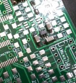
Nice work, it appears that a steady hand was used for all of that SMD soldering. What type of analog side solution do you connect it to?
I am stuck with LM2776 that does not seem to work. It should invert usb 5v into negative, but instead it outputs -2V only. I used schematics from datasheet: one 2u2 x7r at the input, one 2u2 x7r at the output, and one 1u x7r as flying capacitor. I tried three different samples and they all misbehave. There is nothing connected to the output or anywhere else. What could I be doing wrong here?
That does seem odd. It is unlikely that you have three defective devices, and the application circuit could hardly be more simple. Some suggestions:
1) Make certain that you have the EN input (pin 4) tied logic high, or to Vin.
2) Feel with your finger whether device is obviously warm to the touch, in which case it may be experiencing thermal shutdown for some reason.
3) Should the above two suggestions pass, try placing a 1k resistor from the output to ground so as to provide a defined load. The datasheet speaks about how the operational mode of the device changes if the output is lightly loaded. It may simply not be able to regulate properly without some loading.
Tried all this already, I am banging my head:
1) When I remove Cout, device is not supposed to work, because there is no cap to hold negative charge - yet, Vout goes as low as -4.4V!
2) EN is tied to +5V, no doubt about it
3) Tried with different resistors on the output (1k and 100R), but absolute value of Vout drops even more.
4) Tried different output caps - lowest voltage is without Cout, and highest is with 10uF: -1.8V
5) I am using three different samples on three different PCBs - there is no way soldering or defective components are on all of them.
6) Even tried soldering LM2776 wrong way, lucky to have USB power protection
7) Device is cold on touch.
8) Gave PCB a good scrub in white spirit to eliminate excess flux.
Device does work on 2MHz, so placement of components might be critical. I have flying cap as close to LM2776 as it can get. Cin and Cout could be closer, they are on the opposite sides of chip connected through GND plane. They are all mounted on top layer as recommended. Caps are 1206 size.
Attachments
Last edited:


Huh, that is going to be a problem. I used kiCad, due to the fact that I have more freedom in making changes to PCB layout directly without need (and option) to back annotate. So I went ahead and made so many changes to PCB directly that I don't have a matching schematics any more. I will have to make one from scratch now, but then I have no idea how to connect it back to PCB. It's a quite a textbook setup, with +-4.75V at the opamp, with TI LDO 4.75V/3.3V regulators on each power pin of each device, and passive I/V. I am thinking about making a variant with AD1955 and active I/V with OPA1612. Voltage inverter is LM2776. No capacitors in the signal path thanks to it.
Happy New Year everyone!
I recently had a chance to compare this little DAC to Cambridge Audio CXN network player, Pioneer network player and Topping D50 through Dynaudio Focus 340 and RMI-FC100. I was expecting to hear at least some difference in such an open setup, but there was none. I also could not hear a difference between 24/192 and 16/44 material. I thought I might be going deaf, so I invited a younger friend of mine who confirmed the findings.
It seems that this DAC still holds its own, so it might be useful to resurrect it and offer PCBs for those who want to build it.
- Status
- This old topic is closed. If you want to reopen this topic, contact a moderator using the "Report Post" button.
- Home
- Source & Line
- Digital Line Level
- Pcm2707/1794 usb dac