Hi Zoran ... I hope you will allow me a couple of comments to your post ...
.. The thing with using an oscilloscope to test for the curve shape is that the oscilloscope may actually intervene quite significantly with the signal measured. Typical oscilloscope probes may have capacitances in the many picofarad range which adds to the capacitance of the IC input + output + traces and thus skews the response seen. One may then use active probes (can be less than one pF capacity) but in many cases these are expensive and still affect the trace + IC signal.
Also, if one adheres to believing in precise timing being important for the sound quality - i.e. low jitter - using different resistors for each trace will give different band-width for each of these traces and thus timing differences between these traces.
Additionally, using a trimmer adds both capacitance and inductance to a trace which again changes the response of the IC + trace in isolation.
Personally I also would not use point-to-point wiring for digital signals where a controlled impedance and low noise emission presumably is key. Digital signals in my experience is a completely different beast from audio analog signals and having the ground plane close to the signal trace leads to MUCH lower crosstalk values than having a wire - say - 1mm above a ground plane. Try e.g. the Crosstalk calculator tap in Saturn - it calculates such values (remember that digital signal rise times are e.g. 5ns).
A PS.: I also wouldn't use long legs (sockets) on digital ICs because it adds inductance to the system - likely particularly relevant in the PSU decoupling pin where even one millimeter length at high frequencies may actually significantly alter the effective decoupling frequency of the capacitor decoupling the PSU pin.
Well, this is my approach - there of course are many other approaches. And you may also already know this ... In any case - good luck with your endeavors ;-)
Jesper
Yes, but it is better to "trim" against the real measurements. For every out-in trace. In this case it is only a few taps... In praxis these values are typically higher. gravitating about 120-150 in some cases 220 ohms.
I am not sure 100%, for my opinion it improves a sound result. in every digital circuit. And it worth to spend a time on that. When planning the PCB just put blank dmd R at the line. After trim each for right value against the scope.
.
(I did the test plates with point to point links. Want to use no-soldering method but it is hard to obtain special sockets with longer legs)
.. The thing with using an oscilloscope to test for the curve shape is that the oscilloscope may actually intervene quite significantly with the signal measured. Typical oscilloscope probes may have capacitances in the many picofarad range which adds to the capacitance of the IC input + output + traces and thus skews the response seen. One may then use active probes (can be less than one pF capacity) but in many cases these are expensive and still affect the trace + IC signal.
Also, if one adheres to believing in precise timing being important for the sound quality - i.e. low jitter - using different resistors for each trace will give different band-width for each of these traces and thus timing differences between these traces.
Additionally, using a trimmer adds both capacitance and inductance to a trace which again changes the response of the IC + trace in isolation.
(I did the test plates with point to point links. Want to use no-soldering method but it is hard to obtain special sockets with longer legs)
Personally I also would not use point-to-point wiring for digital signals where a controlled impedance and low noise emission presumably is key. Digital signals in my experience is a completely different beast from audio analog signals and having the ground plane close to the signal trace leads to MUCH lower crosstalk values than having a wire - say - 1mm above a ground plane. Try e.g. the Crosstalk calculator tap in Saturn - it calculates such values (remember that digital signal rise times are e.g. 5ns).
A PS.: I also wouldn't use long legs (sockets) on digital ICs because it adds inductance to the system - likely particularly relevant in the PSU decoupling pin where even one millimeter length at high frequencies may actually significantly alter the effective decoupling frequency of the capacitor decoupling the PSU pin.
Well, this is my approach - there of course are many other approaches. And you may also already know this ... In any case - good luck with your endeavors ;-)
Jesper
Last edited:
It is not on the sch, 2 f-f are before, in serial. I think HC74. PRE and CLR are at the +V, data of the first f-f is DATA, CLK for every f-f is MCK, from +Q of first f-f to DATA on the second f-f. +Q and -Q inverted data from second f-f are outputs for "conversion".
.
Main role for this "mirrored" topology is to equalize R in output mosfet circuits. Only one of 2 halts per period are working.
.
I put the DATA at booth enable inputs, but it is maybe a good idea to use just one enable input while other can be used for disabling the stages. Maybe I did that I will check and post.
.
(Sorry for explained in words my old comps are a mess and I could not able to draw a sch for what I am talking about...)
.
Thanks for explaining! It was how I thought it was , after you said DATA 1 and 2 were the same. So it is only one channel you are showing in the schematic and the photos, right?
The PS must be extremely quiet (LifePo4 batteries) as there is absolutely no PSRR in the output stage AFAIK.
I will be ordering some chips and try it out and come up with some measurements.
Again, Thanks for sharing.
@Zoran
Could this be used instead of the 74hc540?
http://www.potatosemi.com/potatosemiweb/datasheet/PO74G244A.pdf
Or perhaps this?
http://www.potatosemi.com/potatosemiweb/datasheet/PO74G373A.pdf
Could this be used instead of the 74hc540?
http://www.potatosemi.com/potatosemiweb/datasheet/PO74G244A.pdf
Or perhaps this?
http://www.potatosemi.com/potatosemiweb/datasheet/PO74G373A.pdf
Hi Zoran ... I hope you will allow me a couple of comments to your post ...
.. The thing with using an oscilloscope to test for the curve shape is that the oscilloscope may actually intervene quite significantly with the signal measured. Typical oscilloscope probes may have capacitances in the many picofarad range which adds to the capacitance of the IC input + output + traces and thus skews the response seen. One may then use active probes (can be less than one pF capacity) but in many cases these are expensive and still affect the trace + IC signal.
Also, if one adheres to believing in precise timing being important for the sound quality - i.e. low jitter - using different resistors for each trace will give different band-width for each of these traces and thus timing differences between these traces.
Additionally, using a trimmer adds both capacitance and inductance to a trace which again changes the response of the IC + trace in isolation.
Personally I also would not use point-to-point wiring for digital signals where a controlled impedance and low noise emission presumably is key. Digital signals in my experience is a completely different beast from audio analog signals and having the ground plane close to the signal trace leads to MUCH lower crosstalk values than having a wire - say - 1mm above a ground plane. Try e.g. the Crosstalk calculator tap in Saturn - it calculates such values (remember that digital signal rise times are e.g. 5ns).
A PS.: I also wouldn't use long legs (sockets) on digital ICs because it adds inductance to the system - likely particularly relevant in the PSU decoupling pin where even one millimeter length at high frequencies may actually significantly alter the effective decoupling frequency of the capacitor decoupling the PSU pin.
Well, this is my approach - there of course are many other approaches. And you may also already know this ... In any case - good luck with your endeavors ;-)
Jesper
Hi Jasper in short - Yes. It is ofcourse not laboratory measurements but only handy equipment tryouts. Not so expensive probes
") I took the care decople multiply C directly on the pins. But I did some eperiments with DIP packages they are somehow less tolerant for ground bounces. Also all of these chips are capable to drive 10-15 gates, and usually driving just one or two. That make the outputs as very strong and sufficiant driver resulting in higher bounces, because of the mch less capacitive load. But still some significant reduce of ringing in signal integity can be acheived. And somehow I can say that is better in sound result?
I took the care decople multiply C directly on the pins. But I did some eperiments with DIP packages they are somehow less tolerant for ground bounces. Also all of these chips are capable to drive 10-15 gates, and usually driving just one or two. That make the outputs as very strong and sufficiant driver resulting in higher bounces, because of the mch less capacitive load. But still some significant reduce of ringing in signal integity can be acheived. And somehow I can say that is better in sound result?Remember some of the great devices acomplished with no-soldering tech
and much higher F was present... That deserves special wire, pisol tool, and special sockets.
Last edited:
@Zoran
Could this be used instead of the 74hc540?
http://www.potatosemi.com/potatosemiweb/datasheet/PO74G244A.pdf
Or perhaps this?
http://www.potatosemi.com/potatosemiweb/datasheet/PO74G373A.pdf
I think yes, this 244 is more suitable. But have a look about polarity? I think that 540 are inverters and 244 not. The enable inputs are the same I think. So the analog signal vil be out of the phase. Nothing bad anyway polarity shoud be checked and reversed if needed. Maybe some click occurs because of just one enable input that must be used for data lines.
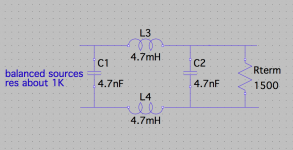
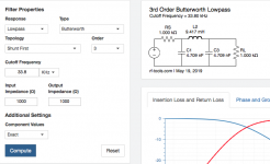
Koldby You said that You have issues about the noise. I have good results with ballanced filter quickly made with a help of these online calc.
RF Tools | LC Filters Design Tool
I used 3rd order simple butt (because of same values...) LC Fo about 33KHz Zo 1K cca.
shunt mode option. in balanced config L is the 1/2 value for the each line C remains the same value. Measured about just -16deg @ 20KHz shift (diskrete R2R balanced dac (Rout 1KHz cca), 4.7nF-4.7mH(in each line)-4.7nF 1.5K load - interstage transformer secondary load 1.5K
Last edited:
What I meant is residual noise in silence. The 1st pic is my music file ripped from vinyl released in the 50'. It has of course relatively large residual noise(-58dB). This is audible for me. But if you can decrease residual noise by 10dB(-58-10=-68), It's gone away, i.e., non-audible. That's why -93dB is completely non-audible for me.
But I have recently found human ear isn't so simple as you wrote. I have been a multibit lover for 20 years like pcm1704. After being obsolete, I managed to design an alternative one with AD9717 which can output both PCM and DSM. PCM is almost -100dB THD while DSM is -120dB THD. I thought DSM is an alternative of PCM mode because I'm a big fan of pcm1704.
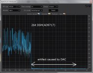
Measurement data and listening test blew away my prejudice. DSM was way better than PCM mode and pcm1704 in my 20 years' memory. Pic.3(PCM) and pic.4(DSM) is distortion caused by DAC. The input is real music(pipe organ) with large spectrum in low frequency, where the bandwidth is limited to 800Hz. If your DAC is perfect, no spectrum exists above 800Hz. Real DAC outputs some distortion caused by real music. Both distortion levels are very small(PCM=94dB, DSM=108dB) but I can completely hear the difference. The lower, the better. If I can manage to have more than -120dB, I will name it a paradise.
Very interesting xx
Would you mind me asking a couple of questions?
Does this distortion fluctuate depending on the signal being replayed through the DAC? I have a theory that the distortion may be related to ground instability related to how much processing is going on in the DAC (gates firing?). This is also related to the power supply quality (stability) feeding the DAC - any info on this?
When you say the difference in sound is obvious - can you say in what way & was it just the bandwidth limited signal you listened to or the full bandwidth signal?
Yes, I'm sure THD+N highly depends on what is being replayed. From this point of view, a single sine wave means only measurement number, can't tell you something about SQ. If you use warble tone(420,440,460,480,500,520, and 540Hz) like the 1st pic, you can see the real performance of your DAC. This is "DAC killer," which is a challenging file for DAC to generate no artifact.
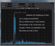
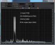
The 2nd pic is FFT of YAMAHA CD player CD-S2000. A single sinewave(L ch) is a standard performance of 44kHz/16bit. Rch(warble tone) has many IMD and harmonic distortion worse than Lch. This is probably poor PCB implementation. Warble tone requires stable ground and power, but two-layer PCB can't offer the optimum environment. Real music file wants further stability because it has much spectrum than simple warble tone. That's the reason 1kHz sinewave tells you nothing about SQ.
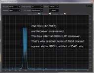
The 3rd pic is my DIYed DAC(AD9717) configured to 2bit DSM. It still has some IMD. I don't know "noise floor modulation" claimed by Chord in details. If it means fluctuated noise floor caused by the replayed file, I can agree with him. It strongly dominates SQ. The best DAC to achieve low "noise floor modulation" is 1bit DSM(DSD), the ultimate weapon to decrease it.
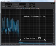
CD-S2000 with poor performance in warble tone generates artifact in real music playback, the 4th pic. My 2bit DSM(the 5th pic) is better than CD-S2000. Noise power of the artifact of CD-S2000 is -98dBFS. It was surprising to me that I could hear the difference between -94dBFS and -108dBFS. My listening test is always normal music, not bandlimited one.
I have a hypothesis that the best is a low artifact with no fluctuation, the worst is a moderate artifact with large fluctuation, and the modest is a large artifact with small fluctuation. The 1st one is well-designed 1bit DSM(I'm now under construction), the 2nd is poor -designed multibit DSM(CD-S2000), and the 3rd is old-school multibit(pcm1704). The human brain may differentiate artifact from music as long as it doesn't fluctuate. If it fluctuates the level, it can be processed as unpleasant music by the brain.
The 2nd pic is FFT of YAMAHA CD player CD-S2000. A single sinewave(L ch) is a standard performance of 44kHz/16bit. Rch(warble tone) has many IMD and harmonic distortion worse than Lch. This is probably poor PCB implementation. Warble tone requires stable ground and power, but two-layer PCB can't offer the optimum environment. Real music file wants further stability because it has much spectrum than simple warble tone. That's the reason 1kHz sinewave tells you nothing about SQ.
The 3rd pic is my DIYed DAC(AD9717) configured to 2bit DSM. It still has some IMD. I don't know "noise floor modulation" claimed by Chord in details. If it means fluctuated noise floor caused by the replayed file, I can agree with him. It strongly dominates SQ. The best DAC to achieve low "noise floor modulation" is 1bit DSM(DSD), the ultimate weapon to decrease it.
CD-S2000 with poor performance in warble tone generates artifact in real music playback, the 4th pic. My 2bit DSM(the 5th pic) is better than CD-S2000. Noise power of the artifact of CD-S2000 is -98dBFS. It was surprising to me that I could hear the difference between -94dBFS and -108dBFS. My listening test is always normal music, not bandlimited one.
I have a hypothesis that the best is a low artifact with no fluctuation, the worst is a moderate artifact with large fluctuation, and the modest is a large artifact with small fluctuation. The 1st one is well-designed 1bit DSM(I'm now under construction), the 2nd is poor -designed multibit DSM(CD-S2000), and the 3rd is old-school multibit(pcm1704). The human brain may differentiate artifact from music as long as it doesn't fluctuate. If it fluctuates the level, it can be processed as unpleasant music by the brain.
Attachments
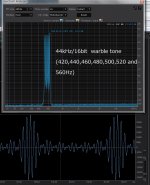
I agree, 1KHz sinewave tests shows only the most egregious distortion issues. Rela music exercises the DAC internals, ground plane & power supply in ways that repeating tones cannot & show far more of value.Yes, I'm sure THD+N highly depends on what is being replayed. From this point of view, a single sine wave means only measurement number, can't tell you something about SQ. If you use warble tone(420,440,460,480,500,520, and 540Hz) like the 1st pic, you can see the real performance of your DAC. This is "DAC killer," which is a challenging file for DAC to generate no artifact.
The 2nd pic is FFT of YAMAHA CD player CD-S2000. A single sinewave(L ch) is a standard performance of 44kHz/16bit. Rch(warble tone) has many IMD and harmonic distortion worse than Lch. This is probably poor PCB implementation. Warble tone requires stable ground and power, but two-layer PCB can't offer the optimum environment. Real music file wants further stability because it has much spectrum than simple warble tone. That's the reason 1kHz sinewave tells you nothing about SQ.
But one of the issues normally encountered when looking at these plots is that the distortion artifacts being so low are dismissed as inaudible & irrelevant. I take the approach that these plots are giving a hint of what is happening along with the music signal processing/replay but it is normally invisible to us
I look on it like this - if we could see the DAC distortion plotted in real time I am certain we would see this DAC distortion fluctuating in both amplitude & spectral content. If we ran the full bandwidth music signal these DAC distortions are still happening but even more so & this is the noise floor modulating in both amplitude & spectral makeup as the music is playing. The missing link is measuring this disturbance & establishing what are the characteristics (modulation depth, spectral makeup) that disturbs our perception of music. I don't say "is audible" because I consider it as having an effect on our perception of music & not audible if such noise floor modulation is played without music on top - i.e. it's a secondary effectThe 3rd pic is my DIYed DAC(AD9717) configured to 2bit DSM. It still has some IMD. I don't know "noise floor modulation" claimed by Chord in details. If it means fluctuated noise floor caused by the replayed file, I can agree with him. It strongly dominates SQ.
What are your best guesses as to why DSD is less prone to this - less bursty underlying processing?The best DAC to achieve low "noise floor modulation" is 1bit DSM(DSD), the ultimate weapon to decrease it.
I figured your listening test was with full bandwidth music but I had to ask, anyway. Yes, it is a bit of a puzzle as to why this is audible - either we are not seeing it's full measured effects when full bandwidth music is playing and/or we are using a simplistic understanding of auditory processing & assuming that -94 to -108dB is not audible?CD-S2000 with poor performance in warble tone generates artifact in real music playback, the 4th pic. My 2bit DSM(the 5th pic) is better than CD-S2000. Noise power of the artifact of CD-S2000 is -98dBFS. It was surprising to me that I could hear the difference between -94dBFS and -108dBFS. My listening test is always normal music, not bandlimited one.
IMO it's the fluctuations that are the heart of the matter & affect our auditory perception - steady state noise below a certain level is inaudible while music is playing.I have a hypothesis that the best is a low artifact with no fluctuation, the worst is a moderate artifact with large fluctuation, and the modest is a large artifact with small fluctuation. The 1st one is well-designed 1bit DSM(I'm now under construction), the 2nd is poor -designed multibit DSM(CD-S2000), and the 3rd is old-school multibit(pcm1704). The human brain may differentiate artifact from music as long as it doesn't fluctuate. If it fluctuates the level, it can be processed as unpleasant music by the brain.
Hi Zoran,
would you mind drawing a simple sketch of your balanced Filter?
Greets, Klaus
Hi Klaus
I used settings from picture butt, hat is for SE. And with 1/2 value of L added in booth lines for balanced. I use butt, but You can use Bessel. Try to get values close to standard. Will be useful to know the internal resistance of the source. For the termination I suggest to measure. IfYou are win user You have great soft called ELSIE for designing filters. I find this online calc tool very helpful
cheers
Attachments
What are your best guesses as to why DSD is less prone to this - less bursty underlying processing?
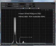
Artifact caused by tough input signal strongly depends on PCB quality and DAC technology. The ideal DAC doesn't generate artifact even if the input is real music, which has significant amplitude change in many frequencies, where ordinary one fails to output the same waveform as the input. The 1st pic is pcm1794 in PCM mode. The 2nd is pcm1792 in PCM mode. The difference is probably the PCB structure. Both are 6bit DSM. The 3rd harmonics around 1.5kHz is the consequence of accuracy error in 6bit DAC inside the chip. It's not easy for the chip to keep high accuracy to prevent 3rd order distortion even if it is well-designed.
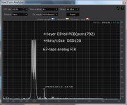
The 3rd pic is pcm1792 in DSD128. Pcm1792 has dedicated converter from DSD to analog(67-taps analog FIR). It's superior to PCM mode because no accuracy error exists in DSD(1bit DSM) though some 3rd order still remains. I don't know where 879.89Hz(2x440Hz) comes from, maybe internal distortion inside the chip or external I/V converter. Anyway, DSD mode is usually superior to PCM mode in modern chips, ESS too. I guess pcm1792 can't make the best of DSD mode because of its architecture. Single low supply voltage forces pcm1792 to have a current output and a user to design distortion-free I/V stage. Recent high output current to ensure high SNR makes the design far difficult. I would recommend the best I/V is no I/V. No I/V topology, as well as no DAC, is the ultimate. Discrete no DAC topologies like Chord or PS audio, i.e., FPGA and discrete transistors.
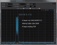
The 4th pic is current my DAC, where FPGA and DAC chip(AD9717) are used for 2bit DSM with 4-taps analog FIR. It's not ideal because the best is FPGA and transistors in DSD(1bit DSM) to achieve low noise floor fluctuation. I'm now under construction what is the best conversion from digital to analog without I/V by transistors. FPGA has already finished successfully because the digital domain is easier to design than the analog domain. Once you have fixed it, you have no problem forever. Emitter coupled circuit like ECL with 16-taps, is a major candidate now.
Attachments
@xx3stksm: Hi again ... This is what I'd call an "intentional" posting because I don't really want to say much other than that I'm intrigued by what you are doing and I hope that you will keep sharing your findings as you progress.
Personally, I also believe that a DAC's ability to "do the same whatever the signal" is very important. One key to this is a very stable clock signal, others - as you touch upon - are PSU related, DAC intrinsic, as well as PCB layout related.
A current conclusion - and frustration, actually - of mine is the apparent need for so many different clock frequencies ... Besides complicating and potentially degrading the clock design it also means that the D/A converter circuit PSU/overall design needs be able to filter a vast range of frequencies equally well - something which rarely is the case, or even possible given the frequency vs. impedance curves of typical filtering capacitors.
So, without being entirely conclusive about this, I see one potentially very attractive D/A solution to be a "single bit/single frequency" conversion system where the signal processing is done outside the DAC itself - and then the DAC "just" handles the creation of this (sufficiently, yet not much) processed signal at one given frequency.
To this end I find your 2 bit DSM interesting because - if I understood you correctly - it is a +, zero, - signal - thus possibly allowing for an output design centered around GND - with very simple electronics.
So, again, I hope you will share your findings ... I will be subscribed ;-)
Cheers to Japan,
Jesper
Hi again merlin ...
So you mean that this is a new firmware for the 768 kHz version ... ??? Do you have a link to where it can be bought?
Cheers & thanks,
Jesper
Yes Jesper, it's this one.
So you mean that this is a new firmware for the 768 kHz version ... ??? Do you have a link to where it can be bought?
Cheers & thanks,
Jesper
It's free, you can download the maintenance tool at Amanero web site and is here to download.
Amanero Technologies
oemtool117
First you need to erase the flash memory of Amanero Amanero Technologies
N.B. You need an original Amanero USB-I2S card.
Amanero Technologies
oemtool117
First you need to erase the flash memory of Amanero Amanero Technologies
N.B. You need an original Amanero USB-I2S card.
Last edited:
- Home
- Source & Line
- Digital Line Level
- The Best DAC is no DAC