Thanks, Marcel. Sounds feasible, will try something along this line (will overall consider how to investigate this).
BTW - just measured DSD64 and the THD is at -113 to -115 dB with a very clean spectrum. Amazing ... DSD512 then rises to -75 dB THD - so I reckon all of this really is VDD decoupling related.
Cheers, Jesper
BTW - just measured DSD64 and the THD is at -113 to -115 dB with a very clean spectrum. Amazing ... DSD512 then rises to -75 dB THD - so I reckon all of this really is VDD decoupling related.
Cheers, Jesper
Exceeding 110dB THD in a single-tap DSD64 implementation can be considered nearly perfect. The gradual degradation seen in DSD128 and DSD256 is likely a result of following the laws of physics.")
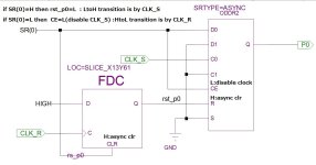
When using a low-speed flip-flop (FF) and configuring an analog FIR with multiple taps, a circuit like the one described below is effective for adjusting rise and fall time. This is a circuit I actually use within an FPGA for analog FIR purposes.
When the input SR(0) is high, the output P0 changes on CLK_S. Conversely, when SR(0) is low, CLK_S is ignored due to clock enable (CE) and P0 changes on CLK_R. Introducing a phase difference between CLK_S and CLK_R aligns the rising and falling edges. Simply replace SR(0) with xSR(0) for inversion. SR(1), xSR(1),SR(2),xSR(2), and so on are the same circuit. However, incorporating numerous logic ICs like 74HC74 might be disadvantageous due to noise and space, favoring the use of CPLD or FPGA.
Attachments
Hi again ... Just a brief post:
@benb : With reference to my question in #2319 please disregard - I think I have sorted it out
@xx3stksm : Thanks for your kind words & your description of the FPGA circuit. I will take a look at it likely late Sunday/Monday - tomorrow & Sunday there are other things I have to attend to (among other things my garden which has grown beyond what I think is acceptable in the last period of time where we have had some rain where I live).
Best wishes for your weekend
Jesper
I'm very interested to use your circuit for adjusting rise & fall time. Excuse my ignorance what ICs are involved?Exceeding 110dB THD in a single-tap DSD64 implementation can be considered nearly perfect. The gradual degradation seen in DSD128 and DSD256 is likely a result of following the laws of physics.
When using a low-speed flip-flop (FF) and configuring an analog FIR with multiple taps, a circuit like the one described below is effective for adjusting rise and fall time. This is a circuit I actually use within an FPGA for analog FIR purposes.
When the input SR(0) is high, the output P0 changes on CLK_S. Conversely, when SR(0) is low, CLK_S is ignored due to clock enable (CE) and P0 changes on CLK_R. Introducing a phase difference between CLK_S and CLK_R aligns the rising and falling edges. Simply replace SR(0) with xSR(0) for inversion. SR(1), xSR(1),SR(2),xSR(2), and so on are the same circuit. However, incorporating numerous logic ICs like 74HC74 might be disadvantageous due to noise and space, favoring the use of CPLD or FPGA.
In devices like FPGAs, most flip-flops typically have clock enables (CE), but this is not common in devices like the 74 series. In such cases, there's no choice but to drive the clock signal using AND gates as a substitute with 74hc74 or 74hc175. In my experience, driving the clock pins of several flip-flops with a small skew to avoid polluting the ground is quite challenging. This is especially true when dealing with analog circuits, like DACs, where there's a mix of analog and digital components. Therefore, if not using an FPGA, the tap count is likely limited to around four.
Just catching up with this thread again with a little more knowledge and understanding. The JLSounds USB Board you are using as far as I can see outputs I2S format. Although it is often referred to here as DSD format. Could one not use an RPI to supply the I2S signal? The DAC I am using now (ProtoDAC) picks up the I2S signal through the RPI GPIO.
MG
MG
It's an interface that can be switched between I2S and raw DSD formats, and the latter is used. I don't know whether a Raspberry Pi's I2S interface can somehow be switched to raw DSD.
Even if it can, another issue is the clock. For these noDACs you need a bit clock with very little far-off phase noise and with very small or preferably no spurious tones (a.k.a. very little systematic jitter). As far as I know, a Raspberry Pi produces fairly strong spurious tones because of the way the audio clocks are derived from a crystal oscillator with an unrelated frequency. The ProtoDAC is far less sensitive to these things.
Even if it can, another issue is the clock. For these noDACs you need a bit clock with very little far-off phase noise and with very small or preferably no spurious tones (a.k.a. very little systematic jitter). As far as I know, a Raspberry Pi produces fairly strong spurious tones because of the way the audio clocks are derived from a crystal oscillator with an unrelated frequency. The ProtoDAC is far less sensitive to these things.
Last edited:
I guess thie answer is for me. I don't want to use FPGA, your post https://www.diyaudio.com/community/threads/the-best-dac-is-no-dac.273474/post-7423752 have any FPGA involved?In devices like FPGAs, most flip-flops typically have clock enables (CE), but this is not common in devices like the 74 series. In such cases, there's no choice but to drive the clock signal using AND gates as a substitute with 74hc74 or 74hc175. In my experience, driving the clock pins of several flip-flops with a small skew to avoid polluting the ground is quite challenging. This is especially true when dealing with analog circuits, like DACs, where there's a mix of analog and digital components. Therefore, if not using an FPGA, the tap count is likely limited to around four.
@gentlevoice , what is the maximum level you use exactly?
I consider a -6dB PCM signal converted to DSD, 0dB DSD.
Some time ago, Marcel made a reference to the maximum number of consecutive "0"`s and/or "1"`s the DSD format allows for. This was written in some DSD format manual?
iirc it allows for something like 24 "0"`s per 32 total bits to be the limit for SACD pressings.
All these rules have their origin in SACD, so DSD64 and if I`m not mistaken then these numbers can scale, maybe not linearly, with rates going up.
Whatever it is exactly, I always generate 24 bits of PCM at the desired frequency, at -6dB and play these back in HQPlayer, converted to DSD, with the volume control enabled and configured to swing between -60dB and + 6dB.
The level at which the output signal starts to distort significantly more, depends very much on logic family (cmos/ecl/ttl), load, it`s own power supply level and decoupling, as well as the level and the wave form of the clock signal used.
So you can choose to optimize for DR or THD.
I never actually tested if THD went up or down depending on the Oversampling Rate, as the assumption always was that if DSD512 would work to satisfaction, the lower rates would at least be the same, or better anyway.
In the beginning I did look at what oversampling rates did with the noise floor, and most CMOS I tried also suffered from rising noise floors when rates went up.
What annoyed me the most in many no-dac designs was the inherent intermodulation products generated at around -20 to -40 dB. Some people have them, others don`t seem to, or don`t notice them?
Trying to fix them resulted in trying various logic families as well. With most of the CMOS I tried, I always got a reasonably clear THD boundary around -5 dB PCM signal level (+1dB DSD), the 2 ecl`s I tried, the SY55852U and the HMC723, could be driven a few dB`s further, but truth be told: it`s very much like comparing the profiles of SET amplifiers.
However, the HMC did sonically very well and with that part, any changes made to the clock circuitry did also translate very well into changes in the subjective SQ department.
The difference in output level, given the forgiveability of clipping the output of the CML part versus the cmos based parts, was quite small despite the lower output voltage swing of the HMC itself.
If you want to try something else than cmos, it might also be something to try for yourself, but they are not really suited to build a large scale FIR with.
The DSD spec is in the second part of the Scarlet Book, https://archive.org/details/super-audio-cd-system-description/SACDspecP2audio_200 contents/
#2322 represents an internal circuit of an FPGA. Even when implementing it discretely, the architecture remains the same. Using synchronous clocks and asynchronous clears, you adjust the timing difference between the rising and falling edges. While it's preferable for both to be synchronous clocks, in the case of spartan6 with two clocks, this driving approach isn't feasible. So, a combination of synchronous and asynchronous is employed. This seems to be the only way, even with discrete components.I guess thie answer is for me. I don't want to use FPGA, your post https://www.diyaudio.com/community/threads/the-best-dac-is-no-dac.273474/post-7423752 have any FPGA involved?
Regarding flip-flops, using single ones like 7w74 might be advantageous compared to dual ones like 74hc74, as they allow for easier power supply bypassing. You can place GND and power supply on inner layers and individually insert 0402(0.1 or 0.01) components.
Hi again,
First I'd like to say that I have decided to complete my experiments with a NoDAC approach - at least for now. I think that the level of performance it currently is at - both measurement-wise & sound-wise is (very) good enough for me ... so now I will complete the PCBs and enjoy listening ... thanks to all of you for commenting & helping out
However, when considering the "development course" I have on several occasions actually been frustrated with "DSD" and the way it varies between different playback softwares - and also within the same software. I have used JRiver, Foobar, HQPlayer, and Tascam Hi-res Editor to play back the same DSD files and even if the settings are identical the distortion levels and distortion distributions vary hugely. There can be as much as 20-30 dB difference between the softwares, and the harmonics levels may also be very different. This makes it sort of tricky to make consistent measurements - something that I have never really experienced with PCM signals.
It may of course be that my measurement setup is not optimized but even when everything is "untouched" (no software or hardware turned on/off) I experienced, particularly from HQPlayer, that the distortion levels could vary as much as 20 dBs.
E.g. the distortions I posted screendumps of in #2313 I have learned were made on what I would call a HQPlayer "good day". The day after, & nothing changed, the levels were less pristine (still good but maybe 5-6 dB more THD).
As it is - and as some of you know - I am not a programmer so I cannot decipher why this can happen (start conditions changing, HQPlayer not meant for static signals, or something else?) - but it has indeed been frustrating to experience this, not least because it took me some time before I found out that this was what was happening. And, then, on the other hand, HQPlayer to my ears still is the best sounding DSD processor of those mentioned above ...
@mterbekke :
I use a free software called wavegene to generate a PCM .wav file. I use many different files but the one I have used for the measurements in #2313 were 1 kHz generated at -1 dB level in wavegene (32 bits, 384 kHz Fs), then added to HQPlayer's playlist and played back at (another) -1 dB in HQPlayer. I have also tried to generate -3 dB levels in wavegene, play back DSD Direct in HQPlayer, and at lower volume settings in HQPlayer. Typically, I would say that there is not really anything surprising about the distortion levels or distortion spectra related to playing back at these different levels - although actually amplifying the DSD signal in HQPlayer caused a significant rise in the distortion level.
My guess has been that the DSD volume limitations may be more relevant to more complex modulators/designs than a NoDAC converter ... ? Thus, with more complex converter structures, maybe inter-stage maximum level limitations may require DSD signals to have a maximum of ones and zeroes? Admittedly, I am not an expert in this.
Even if I have now decided to stop further work on a NoDAC I reckon that there's still room for improvement of this No DAC approach. mterbekke mentions using HMC723 & SY55852U CML FFs with good results ... and I have also considered a single-tap transistor approach inspired by xx3stksm's FPGA & transistor design. Could indeed be interesting but at least for me it is time for this to be completed and then to let the NoDAC rest for a little while ...
Have a fine evening
Jesper
First I'd like to say that I have decided to complete my experiments with a NoDAC approach - at least for now. I think that the level of performance it currently is at - both measurement-wise & sound-wise is (very) good enough for me ... so now I will complete the PCBs and enjoy listening
... thanks to all of you for commenting & helping out However, when considering the "development course" I have on several occasions actually been frustrated with "DSD" and the way it varies between different playback softwares - and also within the same software. I have used JRiver, Foobar, HQPlayer, and Tascam Hi-res Editor to play back the same DSD files and even if the settings are identical the distortion levels and distortion distributions vary hugely. There can be as much as 20-30 dB difference between the softwares, and the harmonics levels may also be very different. This makes it sort of tricky to make consistent measurements - something that I have never really experienced with PCM signals.
It may of course be that my measurement setup is not optimized but even when everything is "untouched" (no software or hardware turned on/off) I experienced, particularly from HQPlayer, that the distortion levels could vary as much as 20 dBs.
E.g. the distortions I posted screendumps of in #2313 I have learned were made on what I would call a HQPlayer "good day". The day after, & nothing changed, the levels were less pristine (still good but maybe 5-6 dB more THD).
As it is - and as some of you know - I am not a programmer so I cannot decipher why this can happen (start conditions changing, HQPlayer not meant for static signals, or something else?) - but it has indeed been frustrating to experience this, not least because it took me some time before I found out that this was what was happening. And, then, on the other hand, HQPlayer to my ears still is the best sounding DSD processor of those mentioned above ...
@mterbekke :
what is the maximum level you use exactly?
I consider a -6dB PCM signal converted to DSD, 0dB DSD.
I use a free software called wavegene to generate a PCM .wav file. I use many different files but the one I have used for the measurements in #2313 were 1 kHz generated at -1 dB level in wavegene (32 bits, 384 kHz Fs), then added to HQPlayer's playlist and played back at (another) -1 dB in HQPlayer. I have also tried to generate -3 dB levels in wavegene, play back DSD Direct in HQPlayer, and at lower volume settings in HQPlayer. Typically, I would say that there is not really anything surprising about the distortion levels or distortion spectra related to playing back at these different levels - although actually amplifying the DSD signal in HQPlayer caused a significant rise in the distortion level.
My guess has been that the DSD volume limitations may be more relevant to more complex modulators/designs than a NoDAC converter ... ? Thus, with more complex converter structures, maybe inter-stage maximum level limitations may require DSD signals to have a maximum of ones and zeroes? Admittedly, I am not an expert in this.
Even if I have now decided to stop further work on a NoDAC I reckon that there's still room for improvement of this No DAC approach. mterbekke mentions using HMC723 & SY55852U CML FFs with good results ... and I have also considered a single-tap transistor approach inspired by xx3stksm's FPGA & transistor design. Could indeed be interesting but at least for me it is time for this to be completed and then to let the NoDAC rest for a little while ...
Have a fine evening
Jesper
Jesper, it seems your problem of changing thd numbers is caused by something related to the layout and/or components used.
Different software causes different noise shaping and this will cause more or less of the oscillation etc.
I can`t remember ever having had much changing thd numbers, not because of the software used, not by using other modulators or filters in hqplayer or Foobar, none.
You just need a few more components that are smaller in value (but the actual goal is size here).
If you`re planning on a new design from scratch, I`d choose the component that you can handle. Meaning: I`d choose Tinylogic if I could handle soldering the stuff, or would choose to let a company populate the board, or at least those parts. If you`re not planning on doing that, I`d choose any tested logic with the footprint you can handle.
In all cases be sure to be able to tweak the power supply of the clock and the flip flops, as well as the resistors used in the signal lines (clock and flip flops).
It is way easier to stick with a known design. If you use hqplayer you can use the AMSDM7 modulator with other no-dac dacs, which will do similar good things like the RTZ coding does.
The RTZ by Marcel is excellent and as we speak further developed, so a very safe bet and doesn`t "need" the hqplayer modulator to be free of potentially weird noises. .
xx3stksm`s dac is a complete solution and has many advantages. Is it possible to build one, or was there a problem with programming the FPGA?
What ever happened to JohnW`s idea of designing a board, anybody know?
@mterbekke : Thanks for your feedback and considering things.
You may be right in this.
FYI I can handle most components including 0402 and SMD components with close to the smallest pitches. The PCBs I make may be tightly impedance controlled where needed including matching the series resistors to the actual IC's impedance. However, normally I would, out of convenience, avoid e.g. the NC7SZ74 in the micropak-8 size (1.6*1.6mm) because it (for me) takes a long time to solder and I find it tricky to handle.
I typically deliberately choose larger low-Dk decoupling components because they have these lower dielectric constants, typically exhibit much lower distortion, and in my experience may typically sound better. Which, also in my experience, is reflected back into the sound of the circuitry in question in almost any case even if it should have an efficient PSRR isolation implemented in the relevant decoupled component.
I do realize there are challenges to this approach - not least that the typically low inductances & capacitances of these components, small or large (SMD1210~1nH), give rise to resonance phenomena which will have to somehow be dealt with. But it is a conscious decision and I think I will stay with it as I still have not found any X7R, tantalum, etc. high-Dk component that I find sound as well (please note: IMHO).
And, yes, with the above in mind I probably still need to be able to better handle lower value decoupling capacitors.
Well, if I understand you correctly - you are referring to the noises that other NoDAC builders have heard? - the thing is that the NoDAC I have been experimenting with does not exhibit any noises at all, as far as I can hear. And I have been listening to it for quite some time now. Maybe a little "thick" in the tonality at low levels - but IMHO still conducive to the ear, and still with a high level of detail.
Yes, I also think Marcel's RTZ DAC is a very fine design, and addtionally, also accessible to make. And to this end I have decided to make a version of it in due time (i.e. as time allows) so as to be able to compare these different approaches to DSD reproduction.
Best, Jesper
it seems your problem of changing thd numbers is caused by something related to the layout and/or components used.
You may be right in this.
If you`re planning on a new design from scratch, I`d choose the component that you can handle. Meaning: I`d choose Tinylogic if I could handle soldering the stuff, or would choose to let a company populate the board, or at least those parts. If you`re not planning on doing that, I`d choose any tested logic with the footprint you can handle.
FYI I can handle most components including 0402 and SMD components with close to the smallest pitches. The PCBs I make may be tightly impedance controlled where needed including matching the series resistors to the actual IC's impedance. However, normally I would, out of convenience, avoid e.g. the NC7SZ74 in the micropak-8 size (1.6*1.6mm) because it (for me) takes a long time to solder and I find it tricky to handle.
You just need a few more components that are smaller in value (but the actual goal is size here).
I typically deliberately choose larger low-Dk decoupling components because they have these lower dielectric constants, typically exhibit much lower distortion, and in my experience may typically sound better. Which, also in my experience, is reflected back into the sound of the circuitry in question in almost any case even if it should have an efficient PSRR isolation implemented in the relevant decoupled component.
I do realize there are challenges to this approach - not least that the typically low inductances & capacitances of these components, small or large (SMD1210~1nH), give rise to resonance phenomena which will have to somehow be dealt with. But it is a conscious decision and I think I will stay with it as I still have not found any X7R, tantalum, etc. high-Dk component that I find sound as well (please note: IMHO).
And, yes, with the above in mind I probably still need to be able to better handle lower value decoupling capacitors.
doesn`t "need" the hqplayer modulator to be free of potentially weird noises. .
Well, if I understand you correctly - you are referring to the noises that other NoDAC builders have heard? - the thing is that the NoDAC I have been experimenting with does not exhibit any noises at all, as far as I can hear. And I have been listening to it for quite some time now. Maybe a little "thick" in the tonality at low levels - but IMHO still conducive to the ear, and still with a high level of detail.
The RTZ by Marcel is excellent and as we speak further developed, so a very safe bet and doesn`t "need" the hqplayer modulator to be free of potentially weird noises. .
Yes, I also think Marcel's RTZ DAC is a very fine design, and addtionally, also accessible to make. And to this end I have decided to make a version of it in due time (i.e. as time allows) so as to be able to compare these different approaches to DSD reproduction.
Best, Jesper
Jesper, when parts become so small they almost disappear under a finger nail, I`m out the door I don`t think I feel good with those footprints and a hot air station.
I like the tweaking and tinkering with novel parts and circuits, but also fighting extremely tiny footprints is a bridge too far.
btw, only the first part was meant as a response to you, the rest of the message was a continuation of my previous email and not specifically directed to you ,as you stated you would stop further work on the no-dac and the weird noises, well some suffer from that. Maybe because in the beginning people used various logic, maybe fakes were among them etc. I have experienced it with the first version of the DSC and also Pavel recommended the AMSDM7 modulator "for best results", so there`s that. It just happens and if it does, a thd measurement of the usual sine at around -60 to -40 dB would show issues.
Marco
I don`t think I feel good with those footprints and a hot air station.I like the tweaking and tinkering with novel parts and circuits, but also fighting extremely tiny footprints is a bridge too far.
btw, only the first part was meant as a response to you, the rest of the message was a continuation of my previous email and not specifically directed to you ,as you stated you would stop further work on the no-dac and the weird noises, well some suffer from that. Maybe because in the beginning people used various logic, maybe fakes were among them etc. I have experienced it with the first version of the DSC and also Pavel recommended the AMSDM7 modulator "for best results", so there`s that. It just happens and if it does, a thd measurement of the usual sine at around -60 to -40 dB would show issues.
Marco
Hi!Hi all,
I have been experimenting quite some with various versions of a NoDAC - basically a balanced FF with an RC filter on the output - and while I can get very reasonable results at DSD64 & DSD128 (-104 dB to - 107 dB THD at DSD128), when I try exactly the same circuitry at DSD256 or DSD512 the distortion goes up substantially (-79 dB THD at DSD256, and -67 dB THD at DSD512) - essentially no matter which FF I use.
Since this rise in distortion level is almost equal for all the FFs (74AC74, NC7SZ74, 74AUP1G74, 74AUC1G74) I have a feel that it may be something "structural" - either related to some for me unknown DSD conversion theory - or in the way I have designed the circuitry.
BTW - a slight digression: These simple NoDACs sound absolutely wonderful - the best I have heard in terms of resolution, tonality, spaciousness, and "naturalness" - so both out of curiosity and slight "bewilderment" I would really like to find out what may be happening here ..??
FYI I have attached a copy of the very simple schematic as well as the PCB layout. I use JLSounds' USB-to-I2S card with NZ2520SDA oscillators so the phase noise performance should be reasonably fine. The AD converter I use for measurements is the AD7760 which is a 24 bit 2.5 MHz Fs balanced input ADC (evaluation board) with a 1 kohm input impedance. Besides the RC filter on the output of the FF (4.7kohm and 5.6 nF to GND - loaded by the 1 kohm) I use no other filtering before entering the signal into the ADC.
If one of you may know what causes this rise in distortion I would much appreciate your feedback.
Cheers & thanks for considering
Jesper
You didn’t say nothing about your hw and sw, maybe the bottleneck is one or both of them?
I mean, maybe your specs are enough to reach dsd128 but it is the natural limit.
Or, and this is a completely different beast, these are pcb design frequency limits.
My 2 cents.
Carmelo
EDIT:
Yeah, I skipped 3 pages of posts…
Last edited:
Could it be related to the characteristics of older FF?I have been experimenting quite some with various versions of a NoDAC - basically a balanced FF with an RC filter on the output - and while I can get very reasonable results at DSD64 & DSD128 (-104 dB to - 107 dB THD at DSD128), when I try exactly the same circuitry at DSD256 or DSD512 the distortion goes up substantially (-79 dB THD at DSD256, and -67 dB THD at DSD512) - essentially no matter which FF I use.
They have the fmax in the range of MHz, and it is needed to have them in the GHz range to avoid distortions at higher DSD rates.
Hi zintolo,
I think there were a couple of reasons why it didn't work too well at higher sample rates. One of them likely was the FFs I was using although my guess is that it is not necessarily the speed but more the similarity of rise/fall times that may be important in determining distortion levels (you may know more about this than I do ;-)). However, I did try a 2.5 GHz FF and it actually didn't perform any better than the ~250 MHz FF versions ...
An additional factor was that my measurement setup wasn't optimal. I was using the AD7760 eval board and for some yet unknown reason it (probably) was "disturbed" by the ultrasonic DSD noise and thus calculated varying distortion levels. Also the buffer I used between the DSD NoDAC and the AD7760 was not ideal. I currently use the Cosmos ADC and an OPA1612 buffer between the NoDAC and the Cosmos and get much more consistent and, I believe, reliable results.
Currently I haven't tried DSD256 or DSD512 though, because my clock setup is a bit unusual - I am feeding the NoDACs without reclocking and my maximum clock rate is 5.6 MHz, i.e. DSD128.
Another factor that in my experience makes a huge difference in the distortion level, is using an RTZ (return-to-zero) topology. And using a balanced configuration. I have not found single-ended outputs to perform very well distortion-wise.
Also, being careful in selecting the right decoupling capacitor values for the FFs. Since the NoDAC structure essentially is very basic it appears to be quite sensitive to the choice of decoupling capacitor value - this can change the distortion levels quite a bit.
Typically, the various FFs are also very sensitive to the loading on their outputs. Finding the right resistor value (as well as the accompanying capacitor value) can make a significant difference.
... my current two cents ...
Cheers,
Jesper
- Home
- Source & Line
- Digital Line Level
- The Best DAC is no DAC