It was the demo version running on a PC. This was maybe a month ago or a bit longer. Didn't see some of the capability you refer to at that time in that version, however it is certainly possible to do (there are other programs that can act as sound devices and route audio between other programs and or other devices).
Didn't get to hear HQplayer in its full glory though, since I was not set up with a really good dac ready to accept high sample rate native dsd. Working on fixing that now, then will have another go at it. Want to hear what it can do.
Awesome. And that explains it: version 4 is only out for a few weeks.
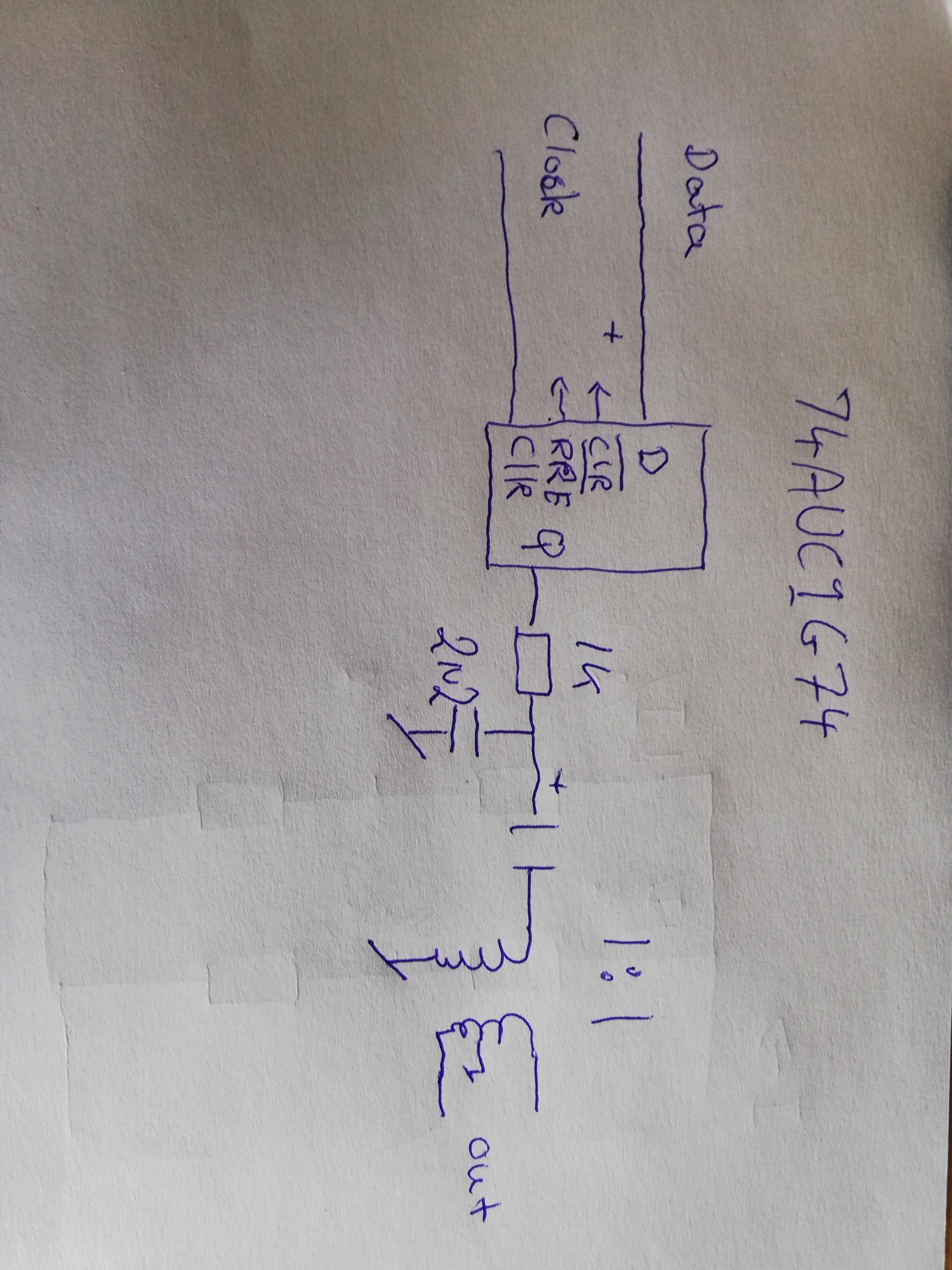
Hi Koldby. Please try to put MCK (master clock) @ flip-flop CLK input pin. OR recklock SCK with MCK and after that clock the data f-f chip.
And repeat clocking with 2 f-f, to avoid metastabile state... F-F chips are usually double inside, use booth of them in cascade.
.
I tried clocking with MCK and 2 f-f and it is better sounding.
cheers
.
Another thing, I think that this 1bit dsd dac need a sort of current conversion. So I suggest to put some say 4.7K serial R at -output of f-f, and to use some Riv 2.2K cca to ground. (or some values to acheive standard pull-down resistor 10K, depends on the driver of f-f output circuit...). After that use Cout and analog filter to interstage xfrm. Take a look at the signalyst dsd dac one bit output.
.
Also I would suggest analog RC terminating secondary of transformer with 15KHz analog signal to eliminate ringing. Take a look at the jensen papers, Find max R and min C without ringing. Then terminate with larger value of R. That is sounding better because of less"compression effect" then just terminate with smaller value of R at the secondary... f-f is not powerful driver...
But it IS mckl @ clk at FF ... What else clk would it be ?
DSD out has only Data L, Data R and CLK..
Current conversion?? No not at all. The output from the FF is voltage, not current out. The Signalyst is quite another principle.
The 74AUC1G74 can easily drive 1 Kohm, why change to 4K7??
My problem is not sound quality but noise. When that is eliminated, I will optimize the transformer loading.
@coldby:
You're running at dsd128 which needs a bitclock of 5.6 MHz, not the masterclock frequency of 22.4 MHz. In essence you're reclocking the dsd data out 4 times faster than needed. If there's any timing error in your dsd left or right signal then your output can be reclocked wrong. This can lead to distortion and noise (which might not show up when using a steady sine test signal).
Another way to test this is to make the output resistance in your dsd left and right datastream larger or smaller (tens, maybe 100's of ohms), but an oscilloscope might give better timing information.
It's also why I choose to always run at dsd512, harder to get right, more revealing in timing errors.
Ok now I am confused. I would think the DSD clk out of the Amanero was the 5.6 Mhz and the MCKL out only was used in PCM mode? I have to check that.@coldby:
You're running at dsd128 which needs a bitclock of 5.6 MHz, not the masterclock frequency of 22.4 MHz. In essence you're reclocking the dsd data out 4 times faster than needed. If there's any timing error in your dsd left or right signal then your output can be reclocked wrong. This can lead to distortion and noise (which might not show up when using a steady sine test signal).
Another way to test this is to make the output resistance in your dsd left and right datastream larger or smaller (tens, maybe 100's of ohms), but an oscilloscope might give better timing information.
It's also why I choose to always run at dsd512, harder to get right, more revealing in timing errors.
Ok now I am confused. I would think the DSD clk out of the Amanero was the 5.6 Mhz and the MCKL out only was used in PCM mode? I have to check that.
It's all in the name: there'a a masterclock and a bitclock. When the stream hits full speed(dsd512), both bitclock and masterclock are the same. Maybe one is later than the other though, I don't know. You might find it is and that might also be the cause of problems if you assume and not check they're exactly the same in frequency and in phase.
With dsd256 the bitclock should be half of the masterclock, dsd128 a quarter etc.
The masterclock is always "good" or "best" regarding jitter specs, the rest gets its reference from it and by doing so might get distorted, you know: jitter, reflections, noise, be delayed etc with regards to the MClk.
Now when reclocking you could use the masterclock, but then you'd have to be sure the data you're reclocking is in very good shape.
You could do that by reclocking the Bitclock first with the Masterclock, and then use that reclocked bitclock to reclock the left and right datastream.
You might even get away with reclocking that last step with the masterclock, if timings allow (oscilloscope or signal to noise measurement might do), or do so as an extra step, after having reclocked it with the bitclock.
Clock, bitclock, masterclock, systemclock. Too many clocks;-)
Afaik Amanero always provides a masterclock output at pin 6, there is also a bitclock output provided, that'd be pin 4 (dsd clock).
Don't you think, that the DSD clk is in good shape, when I easily can measure difference in fast Flip Flops and slow and the fastest are always the ones with the lowest harmonic distortion?
Don't you think, that the DSD clk is in good shape, when I easily can measure difference in fast Flip Flops and slow and the fastest are always the ones with the lowest harmonic distortion?
No.
A sine test signal may make the circuit behave differently from playing music. It doesn't have to, but can. You are having a noise problem which doesn't really show in your measurements, so we're all just shooting from the hip a bit;-)
The rise&fall time speeds of a flip flop is not per sé depending on the stability or speed of the clock provided, but distortion does depend on it a lot afaik. 2 different things.
Why a FlipFlop? Because the distortion figures are lower this way. Why 74UAC1G74, ? Because it measures far better than 74HCT74.
And I just listened to a version with 74HCT74 and it is not as good as the AUC1G.
I made a R/C - L/C lowpass and used coax cables to connect the clk and data to the 74HCT74. Less noise but still far to much. Wonder why?
"Do you use separate HDD cpmeted to PC or laptop?"
I do not understand what you are asking. The noise is there wheter I use an isolator or not on USB and it dosent matter if the files I listen to are on a HDD or on my server (cable- not WiFi)
Where do you connect CLR & PRE?
BTW I used 74 flip-flop and was a bad experience about SQ
Last edited:
It's all in the name: there'a a masterclock and a bitclock. When the stream hits full speed(dsd512), both bitclock and masterclock are the same. Maybe one is later than the other though, I don't know. You might find it is and that might also be the cause of problems if you assume and not check they're exactly the same in frequency and in phase.
With dsd256 the bitclock should be half of the masterclock, dsd128 a quarter etc.
The masterclock is always "good" or "best" regarding jitter specs, the rest gets its reference from it and by doing so might get distorted, you know: jitter, reflections, noise, be delayed etc with regards to the MClk.
Now when reclocking you could use the masterclock, but then you'd have to be sure the data you're reclocking is in very good shape.
You could do that by reclocking the Bitclock first with the Masterclock, and then use that reclocked bitclock to reclock the left and right datastream.
You might even get away with reclocking that last step with the masterclock, if timings allow (oscilloscope or signal to noise measurement might do), or do so as an extra step, after having reclocked it with the bitclock.
Clock, bitclock, masterclock, systemclock. Too many clocks;-)
Afaik Amanero always provides a masterclock output at pin 6, there is also a bitclock output provided, that'd be pin 4 (dsd clock).
All your explanations confirms why I didn't like flip-flop.
Do you know why native sounds better than Dop?
To reclock DSD wich clock have to be used MCLK or BCLK?
VCCWhere do you connect CLR & PRE?
BTW I used 74 flip-flop and was a bad experience about SQ
The problem is that we simple can't recklock with the same F as data. In case of high bit rate 512x the BCK (bit clock or SCK system clock is equal to the present MCK (master clock) at Amanero interface. For recklocking is minimum to have 2 x F at CLK against DATA...
.
BUT if we put 2 x times higher oscillators (then present 22.xxx and 24.xxx) like 44.xxxMHz and 48.xxxMHz AND set the amanero software to 1/2 of MCK. Then we have standard output signals AND we can use direct MCK (double Fo) from oscillators for base clocking F. Oscilators enable and disable from contrroller based on the FS of the song...
.
Mu opinion is that these oscillators should have "sine to square" circuit before enter the controller? This is not complicated circuit and still can managed choosing automatic right clock via enable pins of driver.")
.
Also it is possible in this way to isolate MCK section with own Power supply...
.
BUT if we put 2 x times higher oscillators (then present 22.xxx and 24.xxx) like 44.xxxMHz and 48.xxxMHz AND set the amanero software to 1/2 of MCK. Then we have standard output signals AND we can use direct MCK (double Fo) from oscillators for base clocking F. Oscilators enable and disable from contrroller based on the FS of the song...
.
Mu opinion is that these oscillators should have "sine to square" circuit before enter the controller? This is not complicated circuit and still can managed choosing automatic right clock via enable pins of driver.
.
Also it is possible in this way to isolate MCK section with own Power supply...
All your explanations confirms why I didn't like flip-flop.
Do you know why native sounds better than Dop?
To reclock DSD wich clock have to be used MCLK or BCLK?
I do not think the sound is very good without the FF. Must be a fast FF, or else it is the same as without FF.
And it is NOT in the balanced configuration.
Actually my measurements confirms this, even though good measurements not always are reflected in good sound, I will give you that.
Especially the -40, -50 -60 dB are far better with a fast FF such as 74AUC1G74 than without or with a slow FF and it also sounds far better. IMHO
Why is it that we cannot reclock the data with the same frequency? Seems to me it works just fine, as it measures far better and sounds far better than not to reclock the data...???The problem is that we simple can't recklock with the same F as data. In case of high bit rate 512x the BCK (bit clock or SCK system clock is equal to the present MCK (master clock) at Amanero interface. For recklocking is minimum to have 2 x F at CLK against DATA...
.
BUT if we put 2 x times higher oscillators (then present 22.xxx and 24.xxx) like 44.xxxMHz and 48.xxxMHz AND set the amanero software to 1/2 of MCK. Then we have standard output signals AND we can use direct MCK (double Fo) from oscillators for base clocking F. Oscilators enable and disable from contrroller based on the FS of the song...
.
Mu opinion is that these oscillators should have "sine to square" circuit before enter the controller? This is not complicated circuit and still can managed choosing automatic right clock via enable pins of driver.
.
Also it is possible in this way to isolate MCK section with own Power supply...
I will try to reclock with MCK instead to see if it makes any change in measurements and sound.
Did some more listening and I actually prefer no Flip Flop to a slow Flip Flop, but still 74AUC1G74 is the better than no Flip Flop.All your explanations confirms why I didn't like flip-flop.
Do you know why native sounds better than Dop?
To reclock DSD wich clock have to be used MCLK or BCLK?
Now I changed the Flip Flop clk to MCKL from the amanero on the 74AUCiG74 .The problem is that we simple can't recklock with the same F as data. In case of high bit rate 512x the BCK (bit clock or SCK system clock is equal to the present MCK (master clock) at Amanero interface. For recklocking is minimum to have 2 x F at CLK against DATA...
.
BUT if we put 2 x times higher oscillators (then present 22.xxx and 24.xxx) like 44.xxxMHz and 48.xxxMHz AND set the amanero software to 1/2 of MCK. Then we have standard output signals AND we can use direct MCK (double Fo) from oscillators for base clocking F. Oscilators enable and disable from contrroller based on the FS of the song...
.
Mu opinion is that these oscillators should have "sine to square" circuit before enter the controller? This is not complicated circuit and still can managed choosing automatic right clock via enable pins of driver.
.
Also it is possible in this way to isolate MCK section with own Power supply...
No measurable difference, but I think the subjective noise level was a little lower than before. The sound remain the same as with DSD clk.
Still the best sound..
Why is it that we cannot reclock the data with the same frequency? Seems to me it works just fine, as it measures far better and sounds far better than not to reclock the data...???
I will try to reclock with MCK instead to see if it makes any change in measurements and sound.
It is not possible to recklock data with same F with clk also the same F. F at clk input to f-f have to be at least 2X higher. And same rising edge. Like Mterbekke explained with higher sample rates BCK increasing F up to 22.xxx MHz that is the same as MCK. In that case f-f just stop to operate... Approved in praxis...
.
As for the type of "conversion" it is easy to determinate if it is voltage or current mode. IF it is + data present (from +Q out) and at the say serial R with another R to ground have negative voltage out (Step response going first into the negative axis...) THEN it is current converter. AND data have to be taken from the -Q to have valid phase out. (OR switch secondaries pins if XFRM used...).
IF the signal from +Q have + Step response, than it is voltage device and we have no current conversion at the R from serial R to GND.
.
I measured this.
.
(I don't remember if I post one new concept 1bit "no dac" that I made. With 3 star logic drivers after the f-f. I will post later sch and photo of the device)
One thing that I want to share from the personal experience. Ground bounce or signal integrity is from importance. It can be simplified like adding R between the digital circuits. AND decouple addition to standard 100nF with addition of 10nF + 1nf. Every connection line have to be "trimmed" to eliminate ringing at the edges. Put the scope to 100MHz range and et the trimmer of say 470ohm value which is showing good edges replace with dmd R direct to output pin of the IC. (It could be not small for instance in shift register with HC164 in my sdiskrete I2S dad it is 220-240 ohm). And it depends of many other things so it should be done individually for each pcb or IC...
- Home
- Source & Line
- Digital Line Level
- The Best DAC is no DAC