I stand corrected ")
I used the formula for charging also for discharging the capacitor.
Discharging is as U(t)= U exp(-t/(R C)).
With that we get from the data then C=1200pF.
And with that capacity we get thus as internal resistance 625 Ohm, so the contribution of the DAC ladder only.
So we do not need to think about doing the powersupply better.
It is really hard to find a flaw in Sorens design or specs
Last edited:
AS far as the output low pass filter:
Is there any need for it to be where it is? Why not remove the capacitor on the board and place a filter of your choosing at the output? Not sure if removing the resistor would be necessary. Or just consider the value of the resistor when calculating what is required. It will be in parallel.
Not sure if anything is after the filter which would remove the influence of the shunt resistor on the board.
Your choice of resistor and capacitor becomes wide open and much easier to change. Better than taking chances with soldering on the board several times.
zfe,
Would you do me a huge favour and take a look at a sawtooth with the stock filter and your reduced filter. It appears that the stock filter - and two of my filters that I've checked - are clipping the peak of the sawtooth with FS input and V+00, but I'd appreciate verification from someone with decent gear.
My "scope" is a bitscope micro - BitScope Model 5 | A tiny USB Mixed Signal Oscilloscope - so my measurement capabilities are very limited.
Add: I've adjusted one of my filters to a gain of x7.8 and it looks like that significantly reduces the "chopped top" on the Sawtooth signal.
AddAdd: Dropped to x7.5 and sawtooth is looking better but it appears the peaks on square waves are being chopped. I've had to drop the output level in signal suite to around 87% to eliminate the clipping.
cheers
Paul
Last edited:
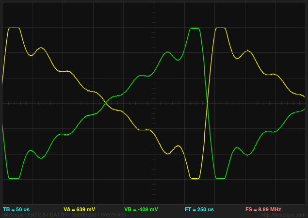
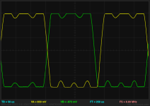
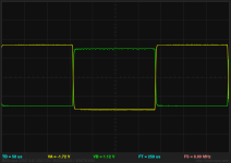
These are screen dumps from bitscope. FS output from SignalSuite, 3000hz sawtooth and square waves. This shows the default Soekris filters, and 44.1khz sampling rate.
You can see the clipped peaks to the waveforms. Sine wave is perfectly fine, so not shown.
This is one of my filters with the gain dropped to x6 - square wave is still clipping at x7.
As I said I'm not 100% confident about the quality of the measurements, so if someone can verify or otherwise it would be appreciated.
The bitscope should handle 12V input but this seems to be clipping at 2V rms.
Attachments

Last edited:
A correction to this.... The voltage was measured between median voltage and the rms voltage so the clipping is occurring at 4Vrms via the balanced outputs. This is slightly under 6V p-p.seems to be clipping at 2V rms.
http://www.ap.com/kb/show/367#soundadvice
However, digital square waves are useful for exposing certain flaws peculiar to digital systems. For example, systems engineered with inadequate headroom may overload when stimulated with full-scale digital square waves. This is a common problem in interpolation filters.
Last edited:
You can see the clipped peaks to the waveforms. Sine wave is perfectly fine, so not shown.
YEs, this looks like there is some clipping, but I'm not sure if it is the Gibbs effect or genuine clipping.
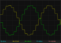
This waveform though shows some interesting behaviour in the negative half of both waveforms - it crosses zero in a strange place in the middle yellow waveform and the ripple is flatter in the second half of both the yellow and green traces.
So this is interesting- the NOSfullbypass 1 doesn't clip when I manually adjust the volume up via the serial manager. I set it to +10 and it is fully usable.
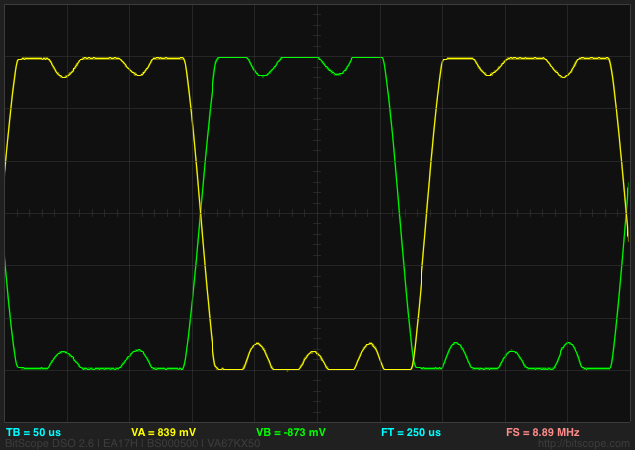
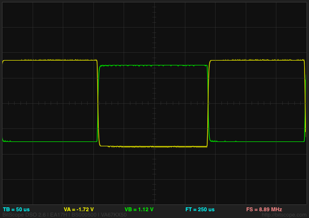
Square waves don't show the "Gibbs phenomena" on NOS DAC's so it's not an issue.
Nice and clean square wave. That is the high point of NOS measurements
Not sure why there is a level difference between the two... but never mind.
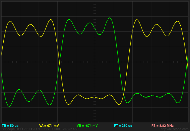
Sine waves are not so pretty...
NOSfullbypass1 is 12-18dB down on the correct 8 x 1 implementation of a NOS filter, so you can probably crank it all the way to a Spinal Tap-esque "but look this one goes to 15, man" and not get any clipping....
Attachments
Square waves don't show the "Gibbs phenomena" on NOS DAC's so it's not an issue.
Nice and clean square wave. That is the high point of NOS measurements
The high point of NOS measurements is between my ears!
YEs, this looks like there is some clipping, but I'm not sure if it is the Gibbs effect or genuine clipping.
This waveform though shows some interesting behaviour in the negative half of both waveforms - it crosses zero in a strange place in the middle yellow waveform and the ripple is flatter in the second half of both the yellow and green traces.
There is a very, very good reason I asked for someone to try to replicate on decent gear. Basically I don't have a high level of confidence in the bitscope. I've seen weird behaviour on the bitscope before it's proved to be a non-issue when checked with a "real" scope.
The tests I did seems to show the clipping occurring at rated RMS output for the balanced stage. Clipping disappears when either test signal is reduced or the digital volume is lowered. Again for the reasons stated above I'd like confirmation from someone with a decent scope before I get too excited about it.
That isn't a measurement.
That is an extremely subjective opinion dressed with copious amounts of expectation bias and seasoned to taste with tube induced third harmonics...

Last edited:
Could you provide me wav of those signals? I can measure in oscilloscope or Tektronix am700. Or describe these signals so that I make with Audition.
Square wave clipping is third harmonic distorsión. I have seen different third harmonic distorsión in different filters.
I has made measurements with fuzzmeasure all filters. I can put frequency response, phase, impulse, impulse in dB and distortion of each filter with an analog measure on my audio card.
I think interesting to see distortion measurements. Varies with each filter, Some filters saturated because they increase about 10-20 db distortion of third harmonic in certain frequency bands. Also interesting impulse responses. More interesting impulse response in dB that shows the pre and pos ringing duration in milliseconds.
There are many graphs that occupy much space on the thread. Probably 80 graphs. I dont know if you interested in these graphics in thread or would be better to make a pdf document Web hosted downloadable. Can anyone give me an opinion.
I could put it all this weekend, it takes me time to capture all those screens.
That isn't a measurement.
That is an extremely subjective opinion dressed with copious amounts of expectation bias and seasoned to taste with tube induced third harmonics...
Filter NOS impulse response is the most perfect of all filters without pre pos ringing energy.
It would be my pleasure, but I am away from my test equipment till probably end of the month.zfe,
Would you do me a huge favour and take a look at a sawtooth with the stock filter and your reduced filter. It appears that the stock filter - and two of my filters that I've checked - are clipping the peak of the sawtooth with FS input and V+00, but I'd appreciate verification from someone with decent gear.
But there is no real need for measurement, I think. The done measurements (of the worst case) shows that the signal looks as predicted by the theory (within the limits of my equipment), especiallay there is no hardware induced clipping and the only hardware effect is the final analog filter (so we can calculate shape of the output signal sample per sample if needed).
... That is if we assume there are no software impementaion faluts and that we stay in the computaional savety overhead of the "3-4 bits" with the intermediate signal levels.
In this case we do not even to simuate the output, but can simulate the filter in the digital domeain only, to decide if there is clipping.
This can perhaps be done with sox (I think) as you did.
Or "by hand", especially for simple test signals. Assume the clipping free signal level is -1 to 1.
Let s[t] be the samples of your test signal, f your filter taps (already multiplied by the multiplier or gain), then the output o[t] is the convolution of s and f.
As example the square wave
First without oversampling (zero insertion)
1.) A square wave of amplitude 1, longer than the filter:
So for entering the wave we are in the situation
s[t]=0 for t<=0; s[t]=1, t>0
The output at time t is the sum of the first t filter taps f, i.e o[t]= Sum_{i=1}^t f
For exiting the square wave we are in the situation
s[t]=1 for t<=0; s[t]=0, t>0
The output at time t is the sum of the all but the first t filter taps f, i.e o[t]= Sum_{i=t+1}^l f.
Conclusion the filter does not clip with a square wave of amplitude 1, longer than the filter, if
neither the absolute value of the sum of the first k taps nor the last k taps exceeds 1 (for all k from 1 to the filter length).
For shorter square waves (with long runs of zero levels betweens the squares), the condition would be that no sum of any consecutive filter taps is greater 1 or smaller -1.
With 8x oversampling we have as new signal s[]= z[0],0,0,0,0,0,0,0,z[1],0,0,0,0,0,0,0,z[2]....
where z[] is the original signal.
Doing analog to the above reasoning, we see we get now conditions, each on filter taps with offset 8.
i.e. no sum f+ f[i+8]+ ... + f[i+8j] for some i,j, is greater 1 or smaller -1.
We can handele FIR1 + FIR 2 similarly. I have not yet given a thought what happens with an intermediate IIR filter.
As I mentioned elsewhere, the condition for that a filter can not clip with ANY signal is that the sum of the absolute values of the filter taps is at most 1.
With 8x oversampling the condition that it can not clip with ANY signal is that non of the eight sums
abs(f[0])+ abs(f[8])+ ...
abs(f[1])+ abs(f[1+8])+ ...
...
abs(f[7])+ abs(f[7+8])+ ...
is greater than 1.
Triangle waves should also be no problem. I can write a little script doing these computations and giving the maximum clip-free gain for these waveforms, in the next days.
The ultimate goal would be a DAM-simulator for the digital output, taking also in account the fixed point arithmetic in the FPGA. To an certain extend this could be done, but at some point we would need implementation details of Soren.
I stand corrected
I used the formula for charging also for discharging the capacitor.
Discharging is as U(t)= U exp(-t/(R C)).
With that we get from the data then C=1200pF.
And with that capacity we get thus as internal resistance 625 Ohm, so the contribution of the DAC ladder only.
So we do not need to think about doing the power supply better.
It is really hard to find a flaw in Sorens design or specs
Hello zfe, I'm confused here ..... what has the analog low pass filter to do with the power supply? From what I can see, there is plenty of room to optimize some of the PSU elements.
Hello zfe, I'm confused here ..... what has the analog low pass filter to do with the power supply? From what I can see, there is plenty of room to optimize some of the PSU elements.
You can compute the equivalent resistance of the DAC (as voltage source) by the measurement of the charge data of the capacitor of the analog low pass filter.
My first calculation was based on a wrong capacity of the capacitor which I had found in some early post of this thread. This calculation indicated that the resistance was higher as the resistance of the DAC ladder alone. This would have meant, that the power supply (i.e. the ensamble of the final voltage regulator and the according bypasses and the shift register), feeding the DAC ladder, had a non neglectable internal resistance. If that would have been the case then it could have been useful to reduce this extra resistance to improve the impulse response of the DAC.
Measuring also the capacity showed that the assumed value was wrong and the internal resistance of the DAC is essentially only the value coming from the DAC ladder, so there is nothing to improve (resistance wise) with the power supply.
Last edited:
Filter NOS impulse response is the most perfect of all filters without pre pos ringing energy.
NOS uses no filtering so it is an oxymoron to call it the "most perfect of all filters".
You can hardly describe something as a perfect filter when it does no filtering.
These are done using the impulse test function of Fuzzmeasure?
What are the traces in the HD charts? Frequency response is fairly obvious but what about the two around -100dB range?
Last edited:
NOS uses no filtering so it is an oxymoron to call it the "most perfect of all filters".
You can hardly describe something as a perfect filter when it does no filtering.
I refer to the different practical measures I have place in the PDF. NOS concentrating more power in less milliseconds.
- Home
- Source & Line
- Digital Line Level
- Filter brewing for the Soekris R2R