Why is this so loud? Using passive volume control after direct output it is 90db at 7:00. Paul's NOS bypass v1 needs to be @ 5:00 for same output.
All other filters have been around 11:00 on analog volume control, except the original NOS which was 2-3:00.
I do not use potentiometer, the gain is always 0 dB.
If you are using volume potentiometer, you should use this NOS-15 filter (-15 dB F1) to avoid saturation at +15 dB.
I do not use potentiometer, the gain is always 0 dB.
If you are using volume potentiometer, you should use this NOS-15 filter (-15 dB F1) to avoid saturation at +15 dB.
I think this misses the point of the 0db to +15dB range. Søren has commented that this is intended as make up gain for very quiet sources, and that for normal usage 0dB is the maximum that should be used. Søren also noted that adding gain will cause clipping if used with sources with adequate levels.
I personally wouldn't be adding attenuation which makes the gain settings a requirement for normal listening rather than an optional boost range as it cripples the intended functionality.
Last edited:
I think this misses the point of the 0db to +15dB range. Søren has commented that this is intended as make up gain for very quiet sources, and that for normal usage 0dB is the maximum that should be used. Søren also noted that adding gain will cause clipping if used with sources with adequate levels.
I personally wouldn't be adding attenuation which makes the gain settings a requirement for normal listening rather than an optional boost range as it cripples the intended functionality.
All of the NOS filters clip except the original one from last month and the new fullbypass 1 (no gain). fullbypass 2, 3, NOS, and NOS-15 all clip in my system.
All of the NOS filters clip except the original one from last month and the new fullbypass 1 (no gain). fullbypass 2, 3, NOS, and NOS-15 all clip in my system.
Fullbypass 2 and especially 3 were experiments to see if the filters would clip due to the added gain, so no surprises there. NOS and NOS-15 really shouldn't clip so there must be another factor in play...
NOS and NOS-15 really shouldn't clip so there must be another factor in play...
Correction, a quick glance at the config indicates that NOS and NOS-15 will both clip badly.
OK, this should be as per Søren's suggested config and minus the x64 gain applied in oneoclock's NOS filters. I've also pasted in pos' revised De-emph filters.
This one shouldn't clip and should be roughly same volume as most filters. with any luck")
This one shouldn't clip and should be roughly same volume as most filters. with any luck
Attachments
This is a slight variation on the above. I'm calling NQR - not quite right - because it's a mid-way position between my (botched) full bypass filter and the Søren-style NOS.
The mod I've made is to alter the filter coefficients from the correct
to the "not quite right"
This only applies to the 44.1 and 48kHz and moves the sinc roll-off up, so the response is only roughly 1dB down at 20kHz. The output using this filter will also be around -6dB on the correct NOS config.
Add: Just had a thought that it might be better reducing the filter taps to 4 rather than adding the 0.0 values. I suspect the zeros make this act as a rectangular filter and will increase distortion.
The mod I've made is to alter the filter coefficients from the correct
Code:
1.000
1.000
1.000
1.000
1.000
1.000
1.000
1.000
Code:
0.000
0.000
1.000
1.000
1.000
1.000
0.000
0.000
This only applies to the 44.1 and 48kHz and moves the sinc roll-off up, so the response is only roughly 1dB down at 20kHz. The output using this filter will also be around -6dB on the correct NOS config.
Add: Just had a thought that it might be better reducing the filter taps to 4 rather than adding the 0.0 values. I suspect the zeros make this act as a rectangular filter and will increase distortion.
Attachments
Last edited:
This is a slight variation on the above. I'm calling NQR - not quite right - because it's a mid-way position between my (botched) full bypass filter and the Søren-style NOS.
The mod I've made is to alter the filter coefficients from the correct
to the "not quite right"Code:1.000 1.000 1.000 1.000 1.000 1.000 1.000 1.000
Code:0.000 0.000 1.000 1.000 1.000 1.000 0.000 0.000
This only applies to the 44.1 and 48kHz and moves the sinc roll-off up, so the response is only roughly 1dB down at 20kHz. The output using this filter will also be around -6dB on the correct NOS config.
Add: Just had a thought that it might be better reducing the filter taps to 4 rather than adding the 0.0 values. I suspect the zeros make this act as a rectangular filter and will increase distortion.
Thanks Paul. I loaded these up with your SA2v2 and look forward to listening this evening!
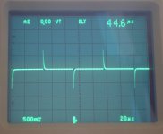
After thinking longer about what I have seen as output of the bypass filter (the output should reach full level (2V), which it does not (0.73V). FIR1=FIR2= one tab 1, multiplier 1), I realized that this is (physical) attenuation due to the "final analog filter"and not a fault of zero-insertion by itself. We have
U_out= U_sig (1-exp(-t/(R C))
so U_out is scaled down by a constant factor.
Here U_sig is the desired signal level, t=1/(64*44.1kHz), C=470pF the capacitance of the filter capacitor, R the internal resistance of the DAC as a voltage source.
So the "problem" is that RC is to high and the DAC needs several similar samples of the final sample rate of about 3MHz, so a FIR2 filter, to come near U_sig.
As we want to filter anyhow and are not designing a MHz AWG signal generator this is not really an issue, I think. But...
The easiest way to get a more text-book like output with the bypass filters, is to lower or remove C.
The harder thing to lower the internal resistance R (perhaps better bypass capacitors at the shift register or lowering/removing the resistor between the voltage regulator and the shift register ... but that is fiddling with the supply of the DAC ladder.
Attachments
Format: signature, samplerate, interpolationrate, type, numbercoefficients, multiplierCorrection, a quick glance at the config indicates that NOS and NOS-15 will both clip badly.
What is multiplier? Is the gain?
It is the number with which all filter coeficents are multiplied. So yes it is gain if >1. With the new version of mkrom.exe the multiplier can also be a float.Format: signature, samplerate, interpolationrate, type, numbercoefficients, multiplier
What is multiplier? Is the gain?
Format: signature, samplerate, interpolationrate, type, numbercoefficients, multiplier
What is multiplier? Is the gain?
Yes, the multiplier is gain.
I've found that you need to keep multiplier * max coefficient value = 1 or lower or the filter will clip.
 , F1 and F2 is bad.
So the "problem" is that RC is to high and the DAC needs several similar samples of the final sample rate of about 3MHz, so a FIR2 filter, to come near U_sig.
As we want to filter anyhow and are not designing a MHz AWG signal generator this is not really an issue, I think. But...
The easiest way to get a more text-book like output with the bypass filters, is to lower or remove C.
Very interesting.
When you say lower C what value would you propose? I think Søren has mentioned the filter cap is 1200pF. If you leave the resistors as is, wouldn't the value of the capacitor need to increase to lower the corner frequency?
I'd been looking at SMD film caps in this position but was dissuaded by the "for reflow only" warnings.
Add: I plugged the formula into excel and had a play, and I can see that you need to reduce the capacitor to increase the output level.
Last edited:
Panasonic 1200pf / 16v PPS in 0603 package should work ok here. Digikey has them for sure.
Not hard to solder, use a good solder & be quick!
Greg in Mississippi
Thanks for the tip. I had thought that something like WBT silver solder would have low enough melting point to avoid dramas.
Very interesting.
When you say lower C what value would you propose? I think Søren has mentioned the filter cap is 1200pF. If you leave the resistors as is, wouldn't the value of the capacitor need to increase to lower the corner frequency?
I'd been looking at SMD film caps in this position but was dissuaded by the "for reflow only" warnings.
Add: I plugged the formula into excel and had a play, and I can see that you need to reduce the capacitor to increase the output level.
I was working on this earlier for the output stage thread. In it Søren said,
"625R Zout, capacitor is 1200 pf ceramic NP0, -3db is then at 212 Khz. NP0/C0G types are supposed to be fine, especially when their effect are way out of the audio band...."
When I calculate for 10,000pf substitution I get 25464.79 hz. My hope is that this will help with the aliasing in the NOS setting and avoid the time smear of the FIR OS. Of course, a .5uf PIO cap is much easier to come by so changing the resistor may also be in order.
Where did you find 1200pF? I only sawI was working on this earlier for the output stage thread. In it Søren said,
"625R Zout, capacitor is 1200 pf ceramic NP0, -3db is then at 212 Khz. NP0/C0G types are supposed to be fine, especially when their effect are way out of the audio band...."
When I calculate for 10,000pf substitution I get 25464.79 hz. My hope is that this will help with the aliasing in the NOS setting and avoid the time smear of the FIR OS. Of course, a .5uf PIO cap is much easier to come by so changing the resistor may also be in order.
You can calculate the internal resistance from the measured data if you know the value of the capacitor....
And the 470 pF capacitor at the output of the R-2R resistor chain take care of anything coming though.
625 Ohm is what you get from the DAC ladder alone as resistance (I measured R=5000 Ohm for a R in the R 2R network) .
With 470pF the internal calculates as about 1600 Ohm, with 1200pF it drops but is still above the ladder-allone resistance.
The value for replacing the capacitor depends on what you want to do.
If you want the bypass filter to have full output. you have to lower the value. If you want more soothing you have to increase.
This is not good thinking. Increasing the capacitor to create a first order filter that low in frequency will have effects in the audio band.I was working on this earlier for the output stage thread. In it Søren said,
"625R Zout, capacitor is 1200 pf ceramic NP0, -3db is then at 212 Khz. NP0/C0G types are supposed to be fine, especially when their effect are way out of the audio band...."
When I calculate for 10,000pf substitution I get 25464.79 hz. My hope is that this will help with the aliasing in the NOS setting and avoid the time smear of the FIR OS. Of course, a .5uf PIO cap is much easier to come by so changing the resistor may also be in order.
Also the output Z of the R2R looks to be fixed and inherent in the DAC design. There is no way you will be able to make use of a 0.5uF capacitor here.
Last edited:
OK, instead of guessing, we also can calculate the value of the capacitor.
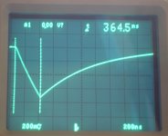
A value to relay on is the resistance of the DAC ladder, I get the 625 Ohm as well my measuring the whole thing as well as by calculation based on one resistor. Moreover that is the number given by Soren.
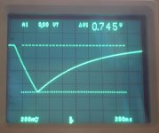
The capacitor is only discharged through the DAC ladder. The time for loosing half the Voltage is about 520ns. Using U(t)= U (1-exp(-t/(R C)) we get for roughtly C=580pF.
Taking in account the inaccuracies of the measurement this makes 470pF the more plausible value.
Using the above formula again with that C, t=1/(64*44,1kHz) rise time and U(t)=0.745V, U=2V, we get as internal resistance of the DAC as voltage source (=DAC Ladder+ internal resistance before the ladder) something about 1600Ohm.
A value to relay on is the resistance of the DAC ladder, I get the 625 Ohm as well my measuring the whole thing as well as by calculation based on one resistor. Moreover that is the number given by Soren.
The capacitor is only discharged through the DAC ladder. The time for loosing half the Voltage is about 520ns. Using U(t)= U (1-exp(-t/(R C)) we get for roughtly C=580pF.
Taking in account the inaccuracies of the measurement this makes 470pF the more plausible value.
Using the above formula again with that C, t=1/(64*44,1kHz) rise time and U(t)=0.745V, U=2V, we get as internal resistance of the DAC as voltage source (=DAC Ladder+ internal resistance before the ladder) something about 1600Ohm.
- Home
- Source & Line
- Digital Line Level
- Filter brewing for the Soekris R2R