I would suggest going rigth to IPv6 to avoid the transition costs.Perhaps I need to do an IPv4 with the corner frequency lifted further again...
") By the way thank you Paul for your hard work.
By the way thank you Paul for your hard work. P.S. I am planning to create a google doc or wiki that will concentrate all available information regarding the filters, graphs, etc, if it is ok with you.
I once had someone with a lot of experience building speakers telling me I was overthinking phase issues. The discussion was with element alignment in an active system with digital room correction and filters. He’s advice was simple. Use the tools at hand with the mind set to ‘Now you hear it, now you don’t‘.
What he meant was that the path from sound source to my ears was not a single sound device. Everything in its path would influence the sound and phase. If something was missing at my listening position with MY ears, tweak the necessary sliders. Problem solved.
Although this mind set simplify phase issue to only be a sound canceling problem it is sane in the sense we will much up phase later on if we intend to use the room correction or crossover function in the dam1021, - like I intend to do.
@Paul – once again thanks a lot. I’ll look into your tips when my head is more clear.
Slightly off-topic, apologies, I remember however, talking with Ted Jordan (very clever man) about phasing with amps, speakers, etc. I measured up to -90-0+90 degree phase shifts across the audible frequency range on my valve amps, yet bang on +5 deg throughout on a pair of TAG McLaren mono 250W amps. Should I worry?
Ted thought the shift per octave I measured would be fine, then reminded me how phase naturally changes between the speaker and what I hear (my ears) depending on frequency/wavelength. Perhaps therefore, it best to not worry too much about low or moderate phase changes? Not sure what level of phase changes we’re talking about here over what sort of range in frequency with the digital filters, so apologies again if my recollections with Ted do not apply.
Ted thought the shift per octave I measured would be fine, then reminded me how phase naturally changes between the speaker and what I hear (my ears) depending on frequency/wavelength. Perhaps therefore, it best to not worry too much about low or moderate phase changes? Not sure what level of phase changes we’re talking about here over what sort of range in frequency with the digital filters, so apologies again if my recollections with Ted do not apply.
I think Mike wants to illustrate with the fan that if you apply a filter to DC the only influence of the phase (to the equally DC) output is its sign.So I guess that you can't really decipher what Mike is claiming beyond his vague allusions to phase correction and kitchen exhaust fans?
OK I take up the gauntlet ... that far that I give an "translation" for humans of relevant parts of the first section. I don't think it is worth the time spent. I do and can not say much about the relevance for the sound.
"filter in closed form": closed form means, you can get "the result" explicit and in simple form from the things you know. I.e. you do not need to numericaly solve a equation to compute "the result", "the result" is not given as recursion, or implicit (i.e. as let x be the solution of x^2-2x+1=0), with a more rigor interpretation there are no integrals, summations,....
In the context with filters I have seen that you want to be able to compute the coefficients of the filter in closed form (as function of your design criteria such as passband,...). Usually the coefficients of IIR filters of higher order are hard to give in closed form. Closed form or not is as such nothing that has something to do with the quality of the filter. Perhaps it helps to see what the influence of your criteria are for the coefficients.
"preserves all of the original samples". One thing a filter does is, if you upsample, to fill the gaps in between the original samples. In general it also alters the original samples.
A FIR filter that has, with x-times oversampling, this property would need to have that, for some fixed number k, the filter coefficients with index x*i+k are all zero but one which is 1. An example, you do 2x upsampling and the new sample is the mean of the one left and right. The filter that does that has coefficients (1, 0.5, 0, 0.5). You have the subsequence (1,0) that corresponds to preserving the original samples.
Non of the filter we had up to now has that property, as far as I see (except NOS and Bypass).
"The filter is also time domain optimized which means the phase info in the original samples are averaged in the time domain".
I think, they want to say that they do not only look at the frequency response of the filter but also at the phase while optimizing. The phase of the filtered upsampled signals should be to some extend similar to the one of the original signal (averaging). I.e. the phase response of the filter should be smooth and not to much away from linear (i.e. to much bent).
"for minimum phase shift as a function of frequency from DC to the percentage of Nyqvist - in our case .968." As "we know" preserving the phase is only important for low frequencies. So the phase optimization needs only to be a design criterion for up certain percentage of Nyqvist.
Here the interpretation of .968 not really clear. As "we know" that preserving the phase is only important for low frequencies, taking it as .968% of Nyqvist (220Hz for 44.1) would make sense. On the other hand why then not say 1%. If he means .968 as a factor, so 96.8% that's a lot more than probably makes sense for the phase but fits with the end of the first section.
OK now we come tho the kitchen fan: "Time domain is well defined at DC - the playback device behaves as a window fan at DC - it either blows (in phase) or sucks (out)."
The filter output of a (co)sine wave is a (co)sine wave of same frequency but possibly other magnitude and phase shift.
In the case of DC f=0 the output thus also DC. As the magnitude is by definition positive, the only effect of the phase behavior of the filter is the sign change.
Last edited:
I was about to post up batch of v3 filters when I had a listen to the -p0 version...
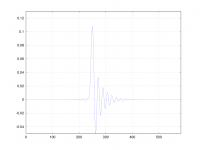
I had a suspicion that the minimum and intermediate phase weren't quite as sexy as the cheers leaders would have you believe. You only have to have a peek at the step response to see what is going to happen.
Changing phase doesn't remove ringing from the filter, it simply shifts it. And there-in lies the rub. If you move all the pre-ringing energy to after the impulse you double the amplitude of the post ringing, and that means the overshoot doubles too. Barf.
This plot shows the step response of the filter coefficients.
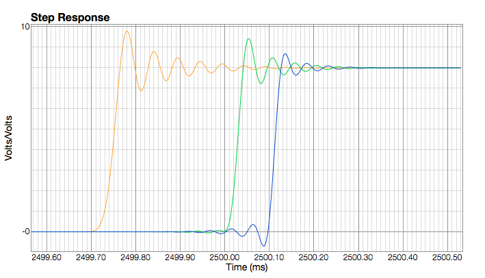
Orange is p0 (-M) , green p30 , and blue p50 (-L).
-p30 sounds ok using volume control, -p0 was just plain awful.
It would be possible to drop the gain on these filter but the output is going to end up very low.
I've attached the folder of filters but be aware that anything less that p25-30 is likely to distort badly.
Thanks a lot for that educational setup. I tried the different phases and in my setup with Volume at v-19 none of the filters clipped or distorted, but the minimal phase filter (p0) sounded significantly better than p50 to my ears. P50 has less transient detail and sounded a little flat compared to p0. Bass quality was also pretty different with p0. I cannot say if better or just different, but the bass felt louder, maybe too loud, with p0. By the way, with p0 the whole signal feels louder than p50, even though it is not, I guess it is the better transient detail. The intermediate filters are in between those two extremes with their qualities, as expected, but until ca. p25 still feel right for me. At the moment I am listening to p20, sounds good to my ears.
Thanks again for all that work.
Tobias
zfe, thank you so much for the explanation. You made it a lot easier to understand.
In your opinion, how important is it to preserve the original samples? Does it really make an audible difference with all other things equal(if that is possible)?
Paul, i really enjoyed the filters you designed, thank you for your contribution!
In your opinion, how important is it to preserve the original samples? Does it really make an audible difference with all other things equal(if that is possible)?
Paul, i really enjoyed the filters you designed, thank you for your contribution!
A justification depends on which model you assume for how a sample is recorded. With upsampling and filtering you want to approach "the real thing", i.e. that what you would have gotten by recording with a higher sample rate (assuming the source bandwith is not higher than fs/2 of the first sample rate fs).In your opinion, how important is it to preserve the original samples? Does it really make an audible difference with all other things equal(if that is possible)?
If you now use as model that your sample is the amplitude of your signal at that precise time, finer sampling would preserve the old samples and just new ones in-between.
If your model is that your sample is some kind of mean-amplitude between the time of the sample and the time one before, your ultimate goal would be that your upsampled and filtered samples are distributed such that they produce the same mean and are not to far away from the original sample. Here there is no reason to preserve the original sample.
So far my theory. I really have no experience in the audio business, so I can not say much to the sound. But even if the samples are not preserved the new one will not be very different. I think the criterion for good or bad sound is somewhere else. On the other hand, it does not harm to preserve the samples, if you can do the rest "right".
Last edited:
To use one my daughters favorite expression. ‘That one was a bitch’. To long since I spend time fighting linux. But finally my GNU Octave Win7 install can do impulse plots. Had to install ‘signal’ package with dependencies.
Noticed one thing thought.
My understanding dlmwrite as used here will write all coefficients loaded into variable b separated by the return character into a new text file?
That is not what happens in my end. Many of the coefficients values are altered in the new file. Don't think thats supposed to happen is it?
An externally hosted image should be here but it was not working when we last tested it.
Noticed one thing thought.
My understanding dlmwrite as used here will write all coefficients loaded into variable b separated by the return character into a new text file?
That is not what happens in my end. Many of the coefficients values are altered in the new file. Don't think thats supposed to happen is it?
Code:
dlmwrite('imp441_test.txt', b, 'delimiter', '\\r');The more I learn even less I understand. Attached text file is Octave script where coefficients are altered when stored into variable named b.
Coefficients is originally created with SoX using –plot octave. File is loaded into Octave editor and script added to create plots.
Compare variable content above to coefficients loaded to variable in the text file below.
Workspace tell us 'b' is stored as double. Are the any rounding going on here?
View attachment OctaveTest.m.txt
Coefficients is originally created with SoX using –plot octave. File is loaded into Octave editor and script added to create plots.
Code:
# name: b
# type: matrix
# rows: 889
# columns: 1
 -2.010210003266341e-009
 -2.681687508273885e-009
 -3.045400115036591e-009
 -2.875689550436774e-009
 -1.993569259395251e-009
 -3.200216763781885e-010
 2.078339831557424e-009
 4.96237337481423e-009
 7.921982239331817e-009
 1.041226923297813e-008
….<snip>
Compare variable content above to coefficients loaded to variable in the text file below.
Code:
b=[-2.0102100032663413e-009
-2.6816875082738845e-009
-3.0454001150365908e-009
-2.8756895504367736e-009
-1.9935692593952505e-009
-3.2002167637818854e-010
 2.0783398315574243e-009
 4.9623733748142296e-009
 7.9219822393318168e-009
 1.0412269232978132e-008
 1.1824905231489546e-008
 1.1588694712620146e-008
….<snip>
Workspace tell us 'b' is stored as double. Are the any rounding going on here?
An externally hosted image should be here but it was not working when we last tested it.
View attachment OctaveTest.m.txt
Thanks a lot for that educational setup. I tried the different phases and in my setup with Volume at v-19 none of the filters clipped or distorted, but the minimal phase filter (p0) sounded significantly better than p50 to my ears. P50 has less transient detail and sounded a little flat compared to p0. Bass quality was also pretty different with p0. I cannot say if better or just different, but the bass felt louder, maybe too loud, with p0. By the way, with p0 the whole signal feels louder than p50, even though it is not, I guess it is the better transient detail. The intermediate filters are in between those two extremes with their qualities, as expected, but until ca. p25 still feel right for me. At the moment I am listening to p20, sounds good to my ears.
Thanks again for all that work.
Tobias
Don't know what was happening on my system then! With p0 trumpets sounded like someone playing a kazoo. Odd.
I think the intermediate and minimum filters potentially "hype" the signal due to the increased overshoot.
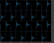
To check this I did a "worst case" test with the filters applied to a 1kHz square wave using SoX. Using p0 as a benchmark I found I had to set the gain to 5.75 to prevent clipped samples.
The rms level of all the output files was identical at -0.79dB, however there was significant difference in the peak level.
p0 = 0dB True Peak
p30 = -0.43dB True peak
p50 = -1.75dB True peak
I can't measure any significant difference "true peak" in up sampled audio, but there may be a perceivable difference when listening.
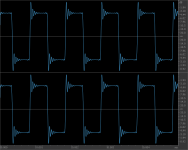
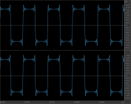
It's interesting that with square wave test the trailing edge is rounded off at p0, p30 has small amounts of ringing prior to the trailing edge that give a slightly "sharper" square.
cheers
Paul
Attachments
Are the any rounding going on here?
Thanks for pointing that out. There is obviously rounding going on.
It's easy to fix by adding the precision pair as per the manual.
Code:
dlmwrite("imp441_deq.txt", b, "delimiter", "\\r", "precision", "%-2.16e" );-2.0102100032663413e-09
-2.6816875082738845e-09
-3.0454001150365908e-09
-2.8756895504367736e-09
-1.9935692593952505e-09
-3.2002167637818854e-10
2.0783398315574243e-09
4.9623733748142296e-09
7.9219822393318168e-09
1.0412269232978132e-08
1.1824905231489546e-08
1.1588694712620146e-08
Not sure how much difference it will make, but no point needlessly rounding.
cheers
Paul
Last edited:
It's interesting that with square wave test the trailing edge is rounded off at p0, p30 has small amounts of ringing prior to the trailing edge that give a slightly "sharper" square.
cheers
Paul
The last image looks like the Gibbs effect to me, i.e. it is a perfect band-limited square wave...
The last image looks like the Gibbs effect to me, i.e. it is a perfect band-limited square wave...
The only variable in those plots is the phase.
There are some differences in the stop band but the filter curves overlay perfectly down to around -70dB.
Hmmm, curious!
I always liked Monty's explanation of the Gibbs effect here https://www.youtube.com/watch?v=cIQ9IXSUzuM (from 17:36). But that appears not to explain your results.
I was always curious about the phase of the filters in the comparisons here SRC Comparisons, I don't know if it is useful for the filter investigations.
Not that curious. Altering phase moves the energy of the ringing in time. Linear phase p50 is an equal distribution, p0 all energy is after the centre of the impulse, p100 all energy is prior to the centre of the impulse. At least that is how I understand it.
Last edited:
schiit's secret sauce filter
0.968 - Mike actually meant 96.8% of the Nyquist freq.:
"The 0.968 of nyquist also gives us a small advantage that none of the off-the shelf FIR filters (0.907) provide: frequency response out to 21.344KHz, 42.688KHz, 85.3776KHz, and 170.5772KHz bandwidth for native 1,2,4, and 8x 44.1KHz SR multiple recordings (...) AND retain the original samples."
So they claim their filter has flat FR up to 21.344k with 44.1k content, retains all original samples (like a NOS filter does), and every interpolated sample has "corrected minimum phase shift as a function of frequency from DC to the percentage of nyquist - in our case .968" (link)
They also claim that all of the above can't be done with freely available tools - take it as a challenge
OK I take up the gauntlet ...
"for minimum phase shift as a function of frequency from DC to the percentage of Nyqvist - in our case .968." As "we know" preserving the phase is only important for low frequencies. So the phase optimization needs only to be a design criterion for up certain percentage of Nyqvist.
Here the interpretation of .968 not really clear. As "we know" that preserving the phase is only important for low frequencies, taking it as .968% of Nyqvist (220Hz for 44.1) would make sense. On the other hand why then not say 1%. If he means .968 as a factor, so 96.8% that's a lot more than probably makes sense for the phase but fits with the end of the first section.
0.968 - Mike actually meant 96.8% of the Nyquist freq.:
"The 0.968 of nyquist also gives us a small advantage that none of the off-the shelf FIR filters (0.907) provide: frequency response out to 21.344KHz, 42.688KHz, 85.3776KHz, and 170.5772KHz bandwidth for native 1,2,4, and 8x 44.1KHz SR multiple recordings (...) AND retain the original samples."
So they claim their filter has flat FR up to 21.344k with 44.1k content, retains all original samples (like a NOS filter does), and every interpolated sample has "corrected minimum phase shift as a function of frequency from DC to the percentage of nyquist - in our case .968" (link)
They also claim that all of the above can't be done with freely available tools - take it as a challenge
Continuing on the theme...
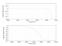
IPv4_p25
- roughly -0.1dB at 19kHz
- -10dB at 22050hz
- fully attenuated at just over 26kHz.
- intermediate phase
Also includes a revised FIR2 which is now flat out past 40kHz and attenuates below 300kHz. FIR2 is linear phase.
SoX settings are included in the .txt file.
IPv4_p25
- roughly -0.1dB at 19kHz
- -10dB at 22050hz
- fully attenuated at just over 26kHz.
- intermediate phase
Also includes a revised FIR2 which is now flat out past 40kHz and attenuates below 300kHz. FIR2 is linear phase.
SoX settings are included in the .txt file.
Attachments
They also claim that all of the above can't be done with freely available tools - take it as a challenge
Sorry I don't have the degree in Math and DSP that requires, so you'll have to gum the Parks McCelland pablum like the rest of us.
Edit: Let me correct that, I don't have a Associate Professor of Mathematics helping me out...
But then again I know from reading the Craven's Apodizing filter papers that he wasn't using Parks McClelland - he used corrected Wilkinson* filters. So I think he's engaging in a bit of over reach. But good to read the quote in context - it always helps.
* http://ieeexplore.ieee.org/xpl/arti...rg/iel1/2211/2865/00087850.pdf?arnumber=87850
Last edited:
They don't say anything about the stop-band behavior.They also claim that all of the above can't be done with freely available tools - take it as a challenge
Without any requirements there it is very easy, just take NOS. (of cause Mike did something more intelligent I suppose)
Last edited:
he used corrected Wilkinson* filters. So I think he's engaging in a bit of over reach. But good to read the quote in context - it always helps.
* IEEE Xplore Abstract - High-fidelity finite-impulse-response filters with optimal stopbands
Is the corrected Wilkinson filter the filter described in the cited paper or a corrected version of that?
- Home
- Source & Line
- Digital Line Level
- Filter brewing for the Soekris R2R