OK - thanks!
//
I should add that using the "norm" option with sox is the optimal way to add headroom.
Code:
sox /path/to/input.wav  -b 24 -r 352.8k /path/to/upsampled_output.wav [b]norm -4[/b] \
upsample 8 [fir /path/to/fir1_coefficents.txt vol 8]
This normalises the volume of the audio data to -4dB prior to upsampling.
Last edited:
Seems like there is no evidence of clipping with the x2 gain correction on the 44.1/48 filters, so I've upped the gain to x4 and done another revision of the .skr
This should mean there is 12dB gain applied by FIR1 and 6dB gain by FIR2 which should make the levels a bit more reasonable and hopefully still avoid issues with clipping.
This should mean there is 12dB gain applied by FIR1 and 6dB gain by FIR2 which should make the levels a bit more reasonable and hopefully still avoid issues with clipping.
Attachments
F1 and F2 NOS filters F1 should be 44,1 samples repeated 64 times. The gain should be 1, except signal attenuation in form of sync from 16 kHz (reconstruction rectangular samples) and measures spectrogram should show a fall in the form of sync with nulls at 44.1, 88.2 ...
Put 0 between samples produce no output signal similar to the original signal in addition to the attenuation x 64.
Put 0 between samples produce no output signal similar to the original signal in addition to the attenuation x 64.
The gain should be 1, .
Nice in theory. But in the case of the DAM1021, praxis proves otherwise.
Never fight the theoryNice in theory. But in the case of the DAM1021, praxis proves otherwise.
")
I measured with an oscilloscope the output of the DAM (SE-out). As input I used a 44.1kHz file containing as samples 0,a,0,-a,0,a,0..., so what you would get as the samples of a sinus signal of 11025kHz of amplitude "a" and phase 0.
With the NOS filter (only one tap 1, gain 1) I saw positive and negative spikes with:
full amplitude --- top pos spike top neg. spike = 1.4V
0.5*full amplitude --- top pos spike top neg. spike = 0.7V
0.25*full amplitude --- top pos spike top neg. spike = 0.35V
With the 2xNOS filter (only one tap 1, gain 2 for FIR1, gain1 FIR2) I saw positive and negative spikes with:
full amplitude --- top pos spike top neg. spike = 1.4V
0.5*full amplitude --- top pos spike top neg. spike = 1.4V
0.25*full amplitude --- top pos spike top neg. spike = 0.7V
So what seems to happen is that amplitudes greater than 1 are reduced to 1.
So if you use to much amplification the top bit(s) of the information get lost, and the more silent parts get lifted (something like loudness).
@ Soren:
There problem with how the DAM handles the maximal negative sample in the PCM data.
Lets say we use 24bit. According the WAV/PCM specifications the negative numbers are the two-complements and x80 00 00 is the the maximal allowed negative number. The DAM (USB-Amareno) reproduces this a zero. x80 00 01 gives the maximal negative spike.
If I look at the x7F FF FF, 0, x80 00 00, 0, x7F FF FF -wav file in audacity, the negative part is displayed, so I suppose the DAM (or the Amareno) does something "wrong".
Last edited:
Nice find again zfe - keep up the good job!
//
//
Never fight the theory
I measured with an oscilloscope the output of the DAM (SE-out). As input I used a 44.1kHz file containing as samples 0,a,0,-a,0,a,0..., so what you would get as the samples of a sinus signal of 11025kHz of amplitude "a" and phase 0.
With the NOS filter (only one tap 1, gain 1) I saw positive and negative spikes with:
full amplitude --- top pos spike top neg. spike = 1.4V
0.5*full amplitude --- top pos spike top neg. spike = 0.7V
0.25*full amplitude --- top pos spike top neg. spike = 0.35V
With the 2xNOS filter (only one tap 1, gain 2 for FIR1, gain1 FIR2) I saw positive and negative spikes with:
full amplitude --- top pos spike top neg. spike = 1.4V
0.5*full amplitude --- top pos spike top neg. spike = 1.4V
0.25*full amplitude --- top pos spike top neg. spike = 0.7V
So what seems to happen is that amplitudes greater than 1 are reduced to 1.
So if you use to much amplification the top bit(s) of the information get lost, and the more silent parts get lifted (something like loudness).
@ Soren:
There problem with how the DAM handles the maximal negative sample in the PCM data.
Lets say we use 24bit. According the WAV/PCM specifications the negative numbers are the two-complements and x80 00 00 is the the maximal allowed negative number. The DAM (USB-Amareno) reproduces this a zero. x80 00 01 gives the maximal negative spike.
If I look at the x7F FF FF, 0, x80 00 00, 0, x7F FF FF -wav file in audacity, the negative part is displayed, so I suppose the DAM (or the Amareno) does something "wrong".
In my opinion, this is equivalent to the situation that the DAM would be clocked at sample rate (so 44.1kHz etc) with no filters applied. This might perhaps with more reason be called "NOS" than zero insertion.I think this is the correct filter NOS DAM1021:
One thing that then schould happen is that you have sinc attenuation at the high frequencies, which at least for 44.1 and 48 would be noticeable.
Last edited:
Never fight the theory
Nice to see the experts have made their way from the armchair to the testbench...
I wasn't. Søren has stated that his processing algorithm had 2-4 bits headroom, so in theory it should have been possible to add at least 12dB gain without causing issues.
Anyway thanks for doing the testing, and picking this up.
Perhaps the answer is in Soren's earlier comment:
I have noticed that most filter generators don't seems to take into account zero insertions, so the coefficients peaks at around 0.125, you then need the multiplier by 8 to scale them to 1....
If the main algorithm is expecting a maximum co-efficent of 1 then multiplying a NOS filter by anything other than one x1 will cause problems. I guess this means the NOS fanciers may have a (level) problem.
My understanding is the filter is processed on a per sample basis, so the zero value samples will still be multiplied x1. What do you achieve by multiplying a sample by 1.000 eight times?
Last edited:
I wasn't. Søren has stated that his processing algorithm had 2-4 bits headroom, so in theory it should have been possible to add at least 12dB gain without causing issues.
It seems that the arithmetic in the FPGA has this headroom (which is good to avoid intermediate calculation errors), but there seem to be no headroom in digital-to-analog signal conversion, where every amplitude (as long as computed within the arithmetic headroom) greater than max-amplitude seems to be to reduced to max-amplitude.
A headroom in digital-to-analog signal conversion would either need to map the normal signal in the middle of the resistor ladder (and so looseing resolution for attenuation), or a longer resistor ladder.
Last edited:
It seems that the arithmetic in the FPGA has this headroom (which is good to avoid intermediate calculation errors), but there seem to be no headroom in digital-to-analog signal conversion, where every amplitude (as long as computed within the arithmetic headroom) greater than max-amplitude seems to be to reduced to max-amplitude.
A headroom in digital-to-analog signal conversion would either need to map the normal signal in the middle of the resistor ladder (and so looseing resolution for attenuation), or a longer resistor ladder.
Easy way to find out is to turn the digital volume down and see if it stops clipping at some point.
I have attached a filter file, which is the original filter of Soren (1021filt) only the FIR filter coefficients scaled down such that there can no longer occur saturation, following the arguments I posted in the main thread:
I do not use the DAM for volume control.
The output is more silent, but with my setup, still high enough at the SE-output for my listening level (and more).
I think the result is more "relaxed" than the original.
I have not yet investigated the impact of (or modified) the IIR deamphasis.
@ Soren
I had another thought about normalizing the FIR parameters. ....
I do not use the DAM for volume control.
The output is more silent, but with my setup, still high enough at the SE-output for my listening level (and more).
I think the result is more "relaxed" than the original.
I have not yet investigated the impact of (or modified) the IIR deamphasis.
Attachments
Last edited:
I do not use the DAM for volume control.
I was putting to you a simple experiment to test if your theory was correct.
The intention is to test if the clipping is occurring in the digital domain or the R2R string. If you can reduce the volume to a point where the clipping ceases the problem is in the r2r. If it clips regardless of the volume then the issue is in the gain coefficients.
You've got an serial convertor hooked up. It a simple matter of typing V+00 to set full volume, V-01, V-02, V-03, etc, etc, to lower the volume.
After all, untested theory is just speculation.
Last edited:
I was putting to you a simple experiment to test if your theory was correct.
The intention is to test if the clipping is occurring in the digital domain or the R2R string. If you can reduce the volume to a point where the clipping ceases the problem is in the r2r. If it clips regardless of the volume then the issue is in the gain coefficients.
You've got an serial convertor hooked up. It a simple matter of typing V+00 to set full volume, V-01, V-02, V-03, etc, etc, to lower the volume.
After all, untested theory is just speculation.
What should be the difference between using the DAC Volume control and using different audio input files with scaled PCM sample values?
None I hope, but I have full control on the input files but no knowledge about the implementation details of the signal processing in the DAC.
Changing the volume, via differently scaled input files, I did (in real world) and it produced the described result as in
But OK I will try the volume controll tomorrw.
Last edited:
Regarding IIR de-emphasis, here are some biquad coefficients that can be used in place of the original ones for better accuracy :
Here is a comparison of Soren's original biquad (in blue) with the theoretical "perfect" de-emphasis amplitude formula (in red) as described here:
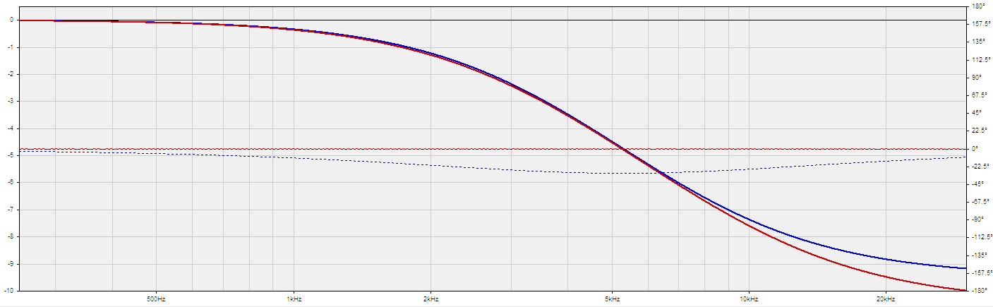
And now the proposed biquad (in blue), still compared to the theoretical formula (in red) :
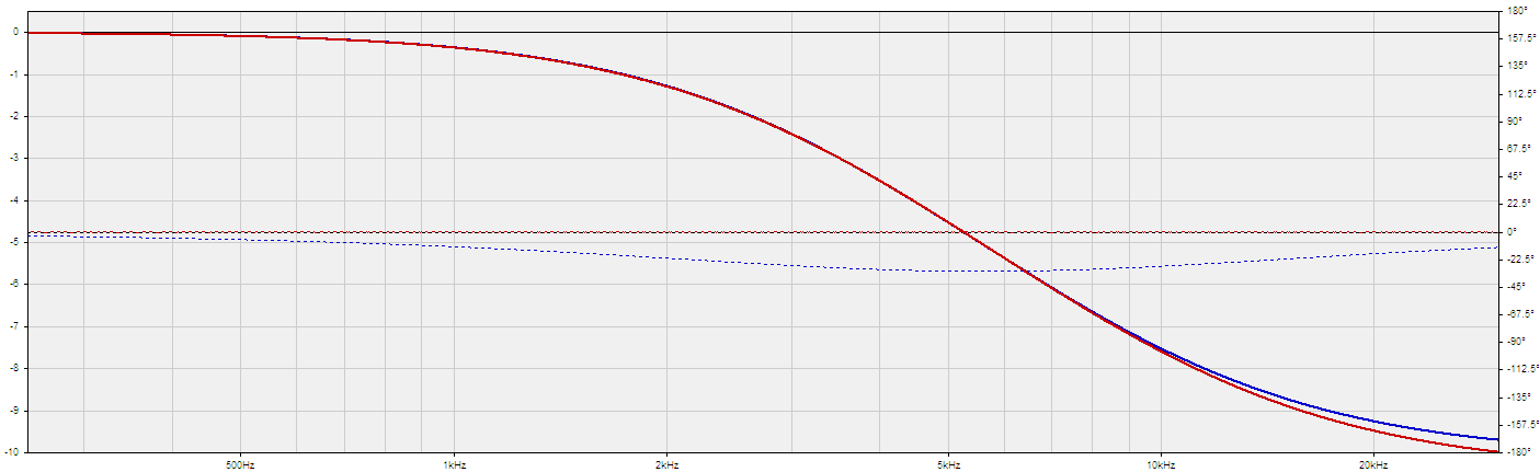
This is as close as I could get with a single biquad.
That said, it looks like variations do exist among CDs on how emphasis was implemented...
Still I think it is a good thing to be as close as possible to the theoretical formula
Code:
dam1021,352800,8,30,5,1
Deemphasis IIR, 352.8 Khz Samplerate, hiself f=5600 Hz, Q=0.485, gain=-10.1 dB
0.331085040573029
-0.577213330670734
0.251294171647457
1.85212451656979
-0.857290398119544

dam1021,384000,8,30,5,1
Deemphasis IIR, 384 Khz Samplerate, hiself f=5600 Hz, Q=0.485, gain=-10.1 dB
0.329617410213504
-0.581107678819127
0.255876017438852
1.86372441280949
-0.868110161642715
Here is a comparison of Soren's original biquad (in blue) with the theoretical "perfect" de-emphasis amplitude formula (in red) as described here:
And now the proposed biquad (in blue), still compared to the theoretical formula (in red) :
This is as close as I could get with a single biquad.
That said, it looks like variations do exist among CDs on how emphasis was implemented...
Still I think it is a good thing to be as close as possible to the theoretical formula
Attachments


Last edited:
No, e.g. with the RME Fireface SPDIF output you can choose if you want the signal with Emphasis(or professional format, ADAT, or non-audio) from the control panel.Q: De-emphasis only work when playing CD from a CD player/drive using s/pdif - right?
//
@Soren:
Speaking of "a single bi-quad", a question I always wanted to ask is, can you cascade several IIR bi-quad filders with the DAM?
As you want to use them for the crossover (+ potentially de-emphasis) this should be the case?
If so, how should the headers look like that they are used cascaded.
Speaking of "a single bi-quad", a question I always wanted to ask is, can you cascade several IIR bi-quad filders with the DAM?
As you want to use them for the crossover (+ potentially de-emphasis) this should be the case?
If so, how should the headers look like that they are used cascaded.
- Home
- Source & Line
- Digital Line Level
- Filter brewing for the Soekris R2R