I've lost the first post I've done... damn!
It's about a tiny 8x TDA1387 DAC, how we can get the best out if it, if it's even worth it...
In short and less organized (than my lost text):
Under 100USD the cased device, Euro/China mains voltage, caps are from old stocks or worse, not the same in each device... (got one for a friend).
CS8416, S/PDIF to DACs converter?
7 pins header "USBinput", any daughter-board needed as my Mac does not see any device when plugged?
STC seems to be a controller of sources selection, or USB input related?
LT1028 in audio path even if I've only seen some in super-regulators, 5 supplies, +/15 opamps, 5/3.3v CS8416, 5V for the TDA1387s?
Cheap PCB but high potential?
All I've written lost for ever... ok guys, look at that and comment. Don't know how's the sound yet as USB failed on my computer and my VRDS is not ready.
Attachments
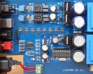
Great pics, very clear.... Soldering all looks done by hand. I agree there's a missing USB module to fit into the SIL connector. I would guess the STC uC is in charge of the front panel display, probably decodes the status lines out of the DIR9001 and turns those into the sample rate LEDs?
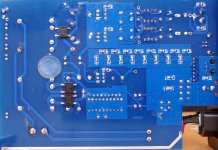
What I like is they've adopted ground 'islands' and aren't using one single ground fill over the whole board. I spent many hours hacking the groundfill on the DAC-AH into manageable pieces so having it partitioned already is a great start Ooh, just noticed there are TL431s being used for regulation - does that mean the heatsinked devices aren't the usual 3-terminal regs, rather discrete transistors? I'm coming to like this more and more
What I like is they've adopted ground 'islands' and aren't using one single ground fill over the whole board. I spent many hours hacking the groundfill on the DAC-AH into manageable pieces so having it partitioned already is a great start
Ooh, just noticed there are TL431s being used for regulation - does that mean the heatsinked devices aren't the usual 3-terminal regs, rather discrete transistors? I'm coming to like this more and more
Last edited:
I've got mine slowly warming up now. Most noticeable on orchestral material is that the HF has the 'false detail' effect which makes it rather fatiguing to listen to over longer periods. Violin strings are overly strident. In my experience this is down to the glitchiness of CMOS DACs generating IMD somewhere in the following opamp. When I originally played with TDA1387s/1545As I tamed this effect with a long string of ferrite beads between the two. Perhaps this time I'll see if the effect can be reduced by attention to the opamp's HF power supply impedance, just for fun...
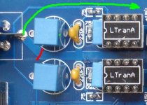
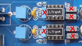
Taking a look at the layout there could be a common-mode noise problem in that there are a couple of 220pF caps feeding directly into the opamps' +ve inputs from a dirty ground (the output ground). So first things first, I shall cut the thick track along the red line and route the output ground back to the trafo (indicated by the green arrow).
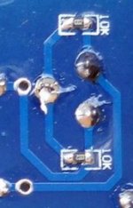
Over on the reverse side, the 10k loads are unnecessarily low (I take it they're to charge the output caps up) so I'll increase them to 1meg.
Over on the reverse side, the 10k loads are unnecessarily low (I take it they're to charge the output caps up) so I'll increase them to 1meg.
Attachments
Last edited:
On opening it up, I discover mine has NE5534s, nothing fancy like LT1028s. I couldn't resist doing a couple of other mods on the first round - those are reducing the supply voltage to the opamps by paralleling a 13k resistor on top of the 10k. I only have 25V ceramics to do the decoupling and 30V of opamp rail isn't required to drive 2VRMS CD levels. Hence now the TL431s are programmed with 2k and 5k6 giving 19V total. Out came the grey rectangular polyesters and in went some 10uF X7Rs (4 per chip), but directly across the power pins (4 and 7), not to AGND. There are already some lytics handling the to-ground decoupling.
Even before I turned up the volume on this it was apparent the depth has improved. Strings are still rather strident but less fatiguingly so. So looks like the ferrites between the DACs and the opamps might be next. Though another possibility is to try some JFET opamps in place of the bipolar 5534s......
Incidentally a warning is in order regards electrical safety. This DAC wouldn't pass CE because its not earthed yet doesn't have classII quality double insulation. In particular I'd recommend some insulating tape on the inside bottom of the case as nothing but air remains between live tracks and the ally chassis.
Tried some AD845s they indeed sweeten the strings somewhat, and now at last the piccolo is sounding more like it should....
Last edited:
Next up is replacing all the pin7 decoupling caps (pin7 is the TDA1387's reference voltage) with 1000uF 'lytics. At present those caps are 10uF ceramics - when I've tried ceramics on my designs I've not much cared for how they sound in this position. Not easy to describe why. Anyway with these 8 caps (on the underside) replaced by 'lytics (on the top as not enough clearance below) I notice an improvement in the LF - more low-level details become apparent, like page turns. Also there was a slight 'nasal' quality to the strings which has diminished.
I need to figure out the schematic for the output stage before I go any further. Haven't worked out if there's passive I/V or active opamp I/V. But its jolly listenable now, nice sense of depth down to lowish frequencies. Not as clean as my Ozone Pagoda (which is my reference) so I wonder how many mods I have left before I have to bite the bullet and install a passive AIF.....
OK so let's state you confirmed that it is a good modding base for a cheap and yet great sounding DAC (anyway it's a bit stupid from me as I don't know compared to wich other DACs... and I hope I don't expect too much in hoping beating the VRDS 10's OEM soundcard...).
As for saftey, there is a long nude track wich is meant to touch the case, very poor contact I see but it's here, just need to wire the earth from ICE socket to that track left alone. But I'll cut plastic sheet wich where used as PSU's internal isolation.
As for USB daughter board, the seller pointed these out:
L108USB daughter card, L4399, L1852 series USB extended sub card
L2706USB combined with L9018, L4399 series of decoder using PCM2706 daughter card
CM6631 24bit 192K USB L4399DAC decoding card used for different steps
I know nothing about data through USB, don't they send, correct error and get bit-perfect? Any card better sounding? Or anywhere else to buy cheap?
I find USB to S/PDIF here and there wich chips references, is teh CS8416 fed with S/PDIF? Sending what to the TDA1387s?
For my own PCB, I have old spare lytics caps, I guess they are dead as shelf life if very short. And still a bunch of fresh SPEC, FM and ZLG. SPEC at pure digital supply (5V CS8416?) ZLG at close decoupling (330µF/16V under the TDAs?)... OPA2132 ready to go. I may wait you report as a crash test dummy before fry mine
Thanks Richard and fellows for having a look.
Last edited:
I took a look at your linked USB modules. If you don't need to send 192kHz to the DAC over USB, I'd go for the first one as its also the cheapest The normal way of implementing USB on Chinese DACs is for the USB receiver to convert to S/PDIF, this output is then routed into the CS8416.
Isn't OPA2132 a dual opamp? No duals here, only singles - you'd need a pair of OPA132s.
The normal way of implementing USB on Chinese DACs is for the USB receiver to convert to S/PDIF, this output is then routed into the CS8416.Isn't OPA2132 a dual opamp? No duals here, only singles - you'd need a pair of OPA132s.
I've buzzed out the connectivity of the opamp-DAC interface now. Its using active I/V with the opamp as a transimpedance amp. The feedback network is 620R in parallel with 2n2 and there's an output filter of 220R and 220pF. The resistors aren't the same value on mine as the silkscreen markings - my SS has 750R and 75R.
Given this new info, its clear why NE5534 is a poor choice - a transimpedance amp needs unity gain stability and 5534 doesn't have that without the Ccomp =22pF (not fitted here).
Back in the days when I was playing with opamp I/V I found LM6172 gave the best result, but I don't have any LM6171s (the singles) so I'll play with some other 'real' CFB amps and report back. At present I'm listening to the AD845s but I've taken out of circuit the 2n2s as I found lower feedback caps sounded better when driven from my AD1955 DAC.
A day's listening and I'm really, really impressed with this DAC. Taking out the 2n2s has considerably reduced the harshness which was apparent on more complex material (orchestral strings, choral) so much that I'm not sure its still there. I'll continue listening.
My favourite opamps for the output stage are still AD845s, I've tried AD844 and AD847 too. All sound very good, just my impression is that AD845 is very slightly sweeter and AD844 makes lower level details slightly more apparent. AD847 sits between the two. Note that to try AD844 you definitely need to remove the 2n2s.
My favourite opamps for the output stage are still AD845s, I've tried AD844 and AD847 too. All sound very good, just my impression is that AD845 is very slightly sweeter and AD844 makes lower level details slightly more apparent. AD847 sits between the two. Note that to try AD844 you definitely need to remove the 2n2s.
Played some more with the power supply this afternoon - found on closer inspection that the TL431s are configured - together with the heatsunk transistors - as 'amplified' shunts (fig31 in TI's DS). The transistor is lowering the shunt's output impedance and boosting the dissipation. These shunts are fed from the res caps via 150R either side. Seeing I've now lowered the supply voltage to around 8V per rail, I've also increased the 150R to 244R (added a couple of 0.5W 47Rs in series with each). Current through this chain of resistors is about 50mA now.
I've marked the caps to remove with a red X - the 2n2s are the blue ones. To the right are the supply decouplers (grey coloured).
I've lowered the supply voltage primarily to be able to get more capacitance out of the X7R ceramics - they lose a substantial proportion of their capacitance under higher bias. It also allows use of physically smaller electrolytics (10V rather than 16V) so its possible to get more capacitance in closer to the ICs. I also would like to experiment with biassing the opamps into classA - this will raise the dissipation so I prefer to minimize that by reducing the rails to what's really necessary, no more.
I think the purpose of having the 2n2s across the feedback resistors is two-fold. First to limit the slewrate and secondly to provide a bit of low-pass filtering. There's a considerable downside in SQ to having them though, which isn't expected under the normal ways of understanding opamp behaviour. I suspect it has something to do with putting glitches on the supply rails when they're present.
Attachments
Last edited:
You're suggesting passive I/V then filter prior to the signal seeing any opamp? That's what I do in my own designs but I'm curious to see what gets lost (or gained) by doing it another way. I've just cobbled together a 2-pole (LC) output filter with NOS correction that I'll try out over the next day or so. Schematic to follow....
- Home
- Source & Line
- Digital Line Level
- TDA1387 x8 DAC: let's check its design, mod it -or not-, play music -or not! :(-