1) either add the 22pF cap (between pins5 and 8) to make the 5534s stable as I/V or swap them out for a unity gain stable amp. Remove the feedback cap.
I'm leaning towards the opamp swap. I've never done anything with opamps before. I know you suggested the AD845---what specific part number? Doing a lookup on Digi-Key shows several AD845 parts. I'm not sure which one is the right one. (And they're kinda pricey, so don't wanna goof it up.)
2) improve decoupling on this opamp - if you keep the current 15V rails you'll need 35V rated caps - find the lowest ESR you can get (Rubycon ZLH; Nichicon PW,HW; NCC KY, KZE)
Does "improve decoupling" mean adding more capacitance, or just adding better caps? Or both?
3) swap out the TDA1387 pin7 decoupling caps (currently ceramics) for 1000uF electrolytics.
That's the one where you and Malefoda both posted pics, with the caps soldered directly to the tda1387 IC pins, right? I believe Malefoda used 470uF caps, which are smaller, making his mod look a little neater. Do you think more (1000uF) is better? Will any old cap work, or are there certain cap attributes I should look for?
Sorry, I warned you guys I'd need some hand-holding!
")
AD845JNZ ($10.55) would be the one to go for. I got my AD845s as free samples many years back so I can't vouch for this choice being best bang-for-the-buck. I had a quick look for others - OPA604 would be worth trying if the budget's tight.
Improving decoupling means adding more capacitance with lower ESR. If you're getting parts from Digikey, these look to be well spec'd : UHW1V821MPD Nichicon | 493-6928-ND | DigiKey
Yeah more is better but why not start out with 470uF and then see if you notice a difference from adding more later? Any cap (except polymer which will be too leaky) is good for this.
AD845JNZ ($10.55) would be the one to go for. I got my AD845s as free samples many years back so I can't vouch for this choice being best bang-for-the-buck. I had a quick look for others - OPA604 would be worth trying if the budget's tight.
Can I just do a straight-up swap of the stock opamps with the AD845s? Or does any of the surrounding circuit need to be modified to work with the new opamps?
Back in post #18, you posted a pic of the stock blue 2n2 caps (right next to the opamps)... and then in post #35:
If you were only to do one mod, the most significant one I'd say for listening pleasure is deleting those feedback caps (2n2s) around the opamps. That kills a lot of the harshness and improves the depth. After that upgrade the opamp supply caps with ceramics and bias the output with a resistor to -VEE (I'm using 2k2 with rails about 8V). Then change the pin7 caps on the DACs which kills most of the nasal quality and improves the LF clarity.
So maybe the stock blue 2n2s should be removed regardless of opamp?
And then, the caps on the other side of the opamps: the four grey ones, and two (IIRC) electrolytic. Do all those together make up the decoupling? Or are some decoupling, and others serve another function?
What I'm getting at, is: should all of them (four grey + electrolytics) be discarded and replaced with the Nichicon UHW1V821MPD you suggested above?
Sorry for all the questions! I'll get there, eventually.
Anyway, I received my 110 -> 220 transformer, and had a few minutes to finally give it an initial spin (in completely stock form). To be honest, I had low expectations, based on my experience with the super cheap Muse tda1543x4... but I was pleasantly surprised. I went straight to my "NOS reference track", where the cymbal ride sounded pretty broken up on the Muse. It certainly wasn't crystal clear on the tda1387, but not at all offensive. Definitely a little "rough" or "scratchy", which, based on the comments above, should get cleaned up with some of these mods. All that based on maybe five minutes of listening.
Point is, I'm definitely encouraged.Can I just do a straight-up swap of the stock opamps with the AD845s? Or does any of the surrounding circuit need to be modified to work with the new opamps?
Yep just swap it out. No other mods are needed for the AD845 to work.
So maybe the stock blue 2n2s should be removed regardless of opamp?
Yes - the 2n2 is what I meant by 'feedback cap' in post 80.
What I'm getting at, is: should all of them (four grey + electrolytics) be discarded and replaced with the Nichicon UHW1V821MPD you suggested above?
Yep, ditch all of those to make room for the new caps.
Sorry for all the questions! I'll get there, eventually.
Hey questions are essential for keeping the thread alive
Anyway, I received my 110 -> 220 transformer, and had a few minutes to finally give it an initial spin (in completely stock form). To be honest, I had low expectations, based on my experience with the super cheap Muse tda1543x4... but I was pleasantly surprised. I went straight to my "NOS reference track", where the cymbal ride sounded pretty broken up on the Muse. It certainly wasn't crystal clear on the tda1387, but not at all offensive. Definitely a little "rough" or "scratchy", which, based on the comments above, should get cleaned up with some of these mods. All that based on maybe five minutes of listening.
Excellent news, thanks for the feedback
I'll have some more details on yet another mod up soon as I've made a small discovery about opamp PSRR in the past couple of days.....
Last edited:
I'll have some more details on yet another mod up soon as I've made a small discovery about opamp PSRR in the past couple of days.....
 ...
...Well, I spent last weekend's minimal free time putting together my Wiener tpa3118 amp, so didn't have a chance to play with the tda1387x8.
...until now, I did the quickest and easiest mod: I replaced the stock opamps with the AD845s Abraxalito suggested. No other mods at all. It's been a couple weeks since I last listened to this, but I can already say it's better. The reason I can say that is because I felt some minor fatigue in my last listening session, brief though it was. I think I would have had some problems listening to it at length. So far I'm only about 20 minutes in, but I'm not getting any hint of that "non physical discomfort" that comes with listening fatigue.
Encouraging. Hopefully I'll get some time this weekend to take a soldering iron to it.
Next up is replacing all the pin7 decoupling caps (pin7 is the TDA1387's reference voltage) with 1000uF 'lytics. At present those caps are 10uF ceramics - when I've tried ceramics on my designs I've not much cared for how they sound in this position. Not easy to describe why. Anyway with these 8 caps (on the underside) replaced by 'lytics (on the top as not enough clearance below) I notice an improvement in the LF - more low-level details become apparent, like page turns. Also there was a slight 'nasal' quality to the strings which has diminished.
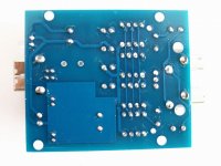
Emphasis added. To which eight underside caps are you referring? My PCB has 16 caps on the underside, directly beneath the tda1387 ICs. Half are labeled "104" and half are labeled "105". Looks like "104" corresponds to pin 8 (right channel output) and "105" corresponds to pin 6 (left channel output). I don't see any caps on the bottom that correspond to pin 7.
I'm waffling between hacking on the pre-assembled build, or leaving it stock, and applying hacks to the bare board, as I build it up. I'm not sure if I can pull of soldering the cs8416 chip though. As best I can tell, it looks like the connection between the cs8416 and the tda1387s is like this:
Code:
cs8416 pin28 OLRCK - tda1387 pin2 WS (word selection)
cs8417 pin27 OSCK  - tda1387 pin1 BCK (bit clock)
cs8417 pin26 SDOUT - tda1837 pin3 DATA (data)
I have to say, I'm pretty impressed with this after doing nothing but the simple op-amp swap. Waaaay better than the Muse tda1543x4 I played with a while ago. I haven't been able to find size- and pin-compatible 110v transformers though. I'd like to chuck the 110-to-220 transformer I'm using. The stock xformer manufacturer's website is kind of lousy, but as far as I can tell, they don't offer 110v equivalents. Grrr.
This PCB also doesn't have holes for mounting via standoffs. Looks to assume you'll be using the right-sized case.
For a guy who's never designed a PCB before: what are my chances of success if I was to copy only the tda1387 + output stage part of this PCB? Input would be I2S (for Amanero or similar), power would be supplied off-board... or maybe, just create a really simple PCB for the tda1387s only? Then go with an off-the-shelf output stage (like something from Peachtree Audio)?
Just kind of rambling/thinking out loud...
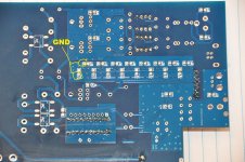
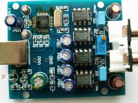
Perhaps you're getting disorientated from flipping the PCB over. The caps I'm referring to are those marked '105'. The '104' caps are wired to decouple the power to the TDA1387, so between 4 (GND) and 5 - there's a via visible leading to pin5. The '105's also have a visible via leading up to pin7. No vias exist for pin6 or pin8 - the tracks paralleling those outputs are on the top side. By all means create a simple PCB - kick off a thread and if you have layout questions I'll chip in.
Perhaps you're getting disorientated from flipping the PCB over. The caps I'm referring to are those marked '105'. The '104' caps are wired to decouple the power to the TDA1387, so between 4 (GND) and 5 - there's a via visible leading to pin5. The '105's also have a visible via leading up to pin7. No vias exist for pin6 or pin8 - the tracks paralleling those outputs are on the top side.
I'm working off the mostly bare PCB, where all I've done so far is solder on the tda1387 chips. I was using my ohm meter to try to get a feel for what goes where.
I just double-checked: if I put a probe on pin 8, and a probe on one of the '104' pads on the other side of the PCB, I get 0 ohms (probes are basically pointing at each other). Same goes for pin 6 and the '105' pads. None of those pads seems to have 0 ohms with pin 5. On '105' I get about 1.7k ohms and pin 7.
I'm part-way through modding one of my PCBs which I've pulled the trafos and main 'lytics out of. I get continuity between the legend side of the '105' cap and pin7 for the TDA1387 nearest the trafos. Also pin5 gives continuity to the side opposite the legend on the '104' cap for the same chip. Pin4 connects to the other side (legended) of this same cap. No continuity to either pin6 or pin8 with those pins. So if both of us are correct our PCBs are totally different.
I get continuity between the legend side of the '105' cap and pin7 for the TDA1387 nearest the trafos. Also pin5 gives continuity to the side opposite the legend on the '104' cap for the same chip. Pin4 connects to the other side (legended) of this same cap. No continuity to either pin6 or pin8 with those pins. So if both of us are correct our PCBs are totally different.
Maybe we're referring to the tda1387 pins differently? I attached a picture showing my understanding of the pins. I think that might be the source of our confusion. As labeled, those backside caps are tied to pins 6 and 8. However, if you imagine IC rotated 180 degress (but the labels stay in place), then the caps are tied to pins 5 and 7.
Attachments
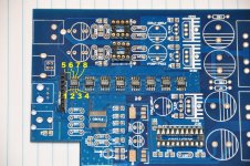
However, if you imagine IC rotated 180 degress (but the labels stay in place), then the caps are tied to pins 5 and 7.
That comment doesn't make any sense.
What I should have said is: if you reverse the numbering on the analog side, i.e., 8-7-6-5 (instead of 5-6-7-8), then we are in agreement.
I'm almost positive my labeling of the digital side is correct, because those tie to the pins of that digital receiver chip, as I described a few posts above.
edit - I just reviewed the data sheet, indeed my labeling is incorrect. It should be 8-7-6-5.
Now it all makes sense. Sorry for the noise and confusion!
Last edited:
OK, here are updated pics with the pins correctly labeled, both on the front and back.
I apologize again, total reading comprehension failure on my part.
Is it possible for a mod to delete my earlier post, or at least remove the pictures? I don't want to send anyone down the same path of confusion.
I apologize again, total reading comprehension failure on my part.
Is it possible for a mod to delete my earlier post, or at least remove the pictures? I don't want to send anyone down the same path of confusion.
Attachments


FYI, I noticed last night that this amp is now available on ebay. Seller doukmall. Here's a current link. I found it by searching for "tda1387 dac". Note the price is $154 with shipping. For reference, I paid about $120 for the completed DAC, a board+parts kit version, shipping and Taobao agent fees.
Interesting is that the listing says to email them for 110v power, which suggests maybe there is a drop-in replacement xformer. I emailed the seller and also the Taobao agent I used to see if they'll give me a manufacturer and part number.
Also, here's another tda1387 DAC. Same seller, only $39 (free shipping). Obviously much simpler: 4x tda1387. Appears to be USB-powered, and direct-out from the DAC chips?
Abraxalito, what are your thoughts on tda1387 direct-output versus having a buffer like the x8 we're talking about in this thread?
When I played with TDA1387 directly output I found the sound depended a lot on what was next in the chain. I put this down to the glitchiness of the power rails when CMOS is on them. Some ICs fed from direct sounded fine, others had what I call 'false detail' added to them which is a big part of the fatiguing sound of typical digital.
I made a version of the Muse TDA1543*4 which had those DACs changed to balanced TDA1387s, then had an AD830 after to go balanced-SE. This didn't add false detail, but using an AD605 did add it. Putting about 20 ferrite beads between the DACs and the AD605 fixed this.
There's also the matter of filtering - in my experience these chips only give of their best when some of the ultrasonics are attenuated. I also prefer the 'NOS droop' to be corrected - that's the roll-off caused by having no oversampling. Going direct out precludes adding these measures.
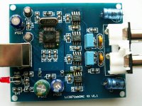
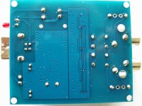
Here are 4x tda1387 and 4x tda1543
I have bought both, 4x tda1387 and 4x tda1543.
(Same ebay seller, link in previous post)
Both are very cheap, and sound great.
Very pure, no false detail, a joy to listen to, also for longer periods.
But I have to admit, USB power is coming from a good linear PSU.
Any simple mods to these dac's ?
(output capacitor’s or clock)
Also, here's another tda1387 DAC. Same seller, only $39 (free shipping). Obviously much simpler: 4x tda1387. Appears to be USB-powered, and direct-out from the DAC chips?
Abraxalito, what are your thoughts on tda1387 direct-output versus having a buffer like the x8 we're talking about in this thread?
I have bought both, 4x tda1387 and 4x tda1543.
(Same ebay seller, link in previous post)
Both are very cheap, and sound great.
Very pure, no false detail, a joy to listen to, also for longer periods.
But I have to admit, USB power is coming from a good linear PSU.
Any simple mods to these dac's ?
(output capacitor’s or clock)
Attachments
- Home
- Source & Line
- Digital Line Level
- TDA1387 x8 DAC: let's check its design, mod it -or not-, play music -or not! :(-