
what is the best way to connect these two entities (Soekris 1021 and amanero combo384) togerther? i mean is there flat cables? would i just drect solder? should I use female pins? can i use that connector in the picture? what is the best way?
You can direct solder. The downside is you lose flexibility/convenience if you want to make changes.
What most people are doing is soldering a "connector" (i.e. male pin header) on each board (both the Soekris board and the Amanero), then use jumper wires (both end female) to make the appropriate connections.
Whatever you do, best practices suggest keeping the I2S wiring (i.e. connection between Amanero and DAC) to 10cm or less. Shorter is better.
what is the best way to connect these two entities (Soekris 1021 and amanero combo384) togerther? i mean is there flat cables? would i just drect solder? should I use female pins? can i use that connector in the picture? what is the best way?
I would advise to use female pin headers. You can solder cables to this and then mount the female part on the Soekris board without soldering. This way, you have a tight connection but still a way to demount. I would use solid core twisted CAT5 wire pairs for I2s. One of the wire pairs should be ground for all connections. And indeed you need to keep them short.
Fedde
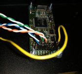
do you mean this?

couild you pleas explain the chain? i will solder this to both the soekris board and the amanero board and then use du pont male pins to on both ends of the cable?
wouldnt that be the same as soldering male headers to both board and then using this cable?
40pcs 10cm Female To Female Dupont Wire Jumper Cable for Arduino Breadboard 992170878780 | eBay
Hi Greg,
You know Duncan's PSU Designer II, do you ?
You can see there the difference in ripple voltage/current spikes of a tPical CRC vs. LCLC supply....it is enourmous. I just converted my filament raw supply from CRC to LCLC and you hear the difference by a wide margin...reason being that the current spikes of a CRC which has 1A DC is like 5A from the diode pov...going down to 0.2A looking at ripple current...this is a lot of noise LESS in your psu, radiating into the whole circuit...this is not theory, I just tried it and this definetely is very audible...
Blitz,
No argument with what you say at all. I totally agree that choke input filtered supplies are the best choice for AC-fed supplies. AND I honestly don't wish to make room for them on this setup at this time... the 8 supplies already there take up a lot of room, adding chokes would add a lot more room.
Also, I'm experimenting with non-AC connected supplies (likely Ultracaps) and suspect I'll be moving to them for ultimate applications where they are suited.
Greg in Mississippi
couild you pleas explain the chain? i will solder this to both the soekris board and the amanero board and then use du pont male pins to on both ends of the cable?
wouldnt that be the same as soldering male headers to both board and then using this cable?
Yes indeed, those are the female pinheaders I meant. i would suggest to cut these headers in (six) pieces of 2 pins. Then solder a twisted CAT5 solid core wire pair to the male part of the 2 pinheader. On the other end of the wire pair also a two pin header needs to be soldered (again to the male part). This way you have created a twisted ground+signal pair that can be mounted to (male) pinheaders on the PCB. For I2s you need three of these twisted cables.
The cables you showed could work, but they are not twisted and I would target for shorter than 10 cm.
I hope it is clear enough, otherwise I need to make an image. Alternatively you can use 4 times 3 pins instead of 6 times 2 pins.
Fedde
I'm interested in building a dac/streamer from the dam1021 v5 board.
To start I can connect a suitable toroidal transformer directly to the board, link a, separately powered, RPi to it through i2s and connect a spdif socket on the back to get up and running in a case with power and source switches?
Eventually I'd want to upgrade the psu section and add a volume control, does the power supply make a good improvement and is digital volume control as good as analogue (I'm building an Audiosector Lm3875 at the moment and could easily add an Alps blue pot to it as the dac will be the only thing connected to the amp)?
I was one of the ones that replaced the 3.3V LDO with sparko discretes and I felt there was indeed a difference, there was an obvious improvement measurably with my scope across the clock 3.3v power. I'm now very interested in upgrading the +/- supplies to the same and feeding them much closer to the 4V super regulator stages. Nice to see it's been done with some apparent success in improvement.
I've finally got round to building the dac, I've put a raspberry Pi 3 in the case with the dac and connected via i2s, I'm using Volumio2 as a player and can get internet radio and mp3 files from my NAS to play but not FLAC files from the same NAS. Any ideas why this would be?
I´m looking for some power supply to finish my Dam1021. Check my request here:
WTB: ultralow noise PS 3.3V and +-12V
Thanks
WTB: ultralow noise PS 3.3V and +-12V
Thanks
You may have a look on Finally, an affordable CD Transport: the Shigaclone story
I already use such to power Amanero and clock section in DAM1021 ver1 with great improvement.
Regards,
Tibi
I already use such to power Amanero and clock section in DAM1021 ver1 with great improvement.
Regards,
Tibi
Last edited by a moderator:
You need to set Volumio's I2S output to 24 or 32 bits.
Thanks, got all the music from the NAS working along with internet radio but still can't get Spotify to make any sound.
Any ideas?

You can power the s/pdif inputs from the 3.3V & 1.2V available on the DAM's power header (J2).
But the I2S input's "dirty" side must be powered from a separate, isolated 3.3V power supply.
In dual-mono, is it reasonable to ground SPDIF to only one board to prevent ground loops? The two board should share the same ground via PSU.
I'm really quite conflicted about my SPDIF implementation. On one hand I don't want to take power from DAM to prevent imbalances between the two boards and also prevent accidents in my input board from damaging DAM since SPDIF is just there for completion sake more or less... On the other hand, if I use the PSU powering ISO USB to power SPDIF inputs, I won't be able to connect GND to the input circuit otherwise I will be shorting signal ground and ISO ground. Soren said somewhere that SPDIF is sensitive and I hope to enable 192Khz transmissions with DA101C and 25Mbps TOSLINK receiver. Would letting 3.3V floating be a problem? Could it cause larger voltage differences over SPDIF ground with all current going through it?
Is there a way out of this...? Thanks!
Last edited:
- Status
- This old topic is closed. If you want to reopen this topic, contact a moderator using the "Report Post" button.
- Home
- Source & Line
- Digital Line Level
- Soekris' DAC implementations