below a minimal digital crossover design, intended for a 2-way active system. input is balanced, outputs are 2ch balanced or bridge drive or 4ch multiway.
input peak led and vol control. I added the extra no-overshoot low-passfilters. opamp is the TS921, board would be 100x60mm. this is similar to the freeDSP publication http://www.dafx14.fau.de/papers/dafx14_sebastian_merchel_freedsp_a_low_budget_ope.pdf
except this one is mono, to be built into the cabinet. code development uses the free sigmadsp tools from AD.
any suggestions for features that keep the design still elegant and simple ?
Attachments
I could, if I can find a decent assembly house. the throughhole parts could be customer specific, like the 2 XLR's, input and loopthrough. I'm considering changing the led in a bicolor one, green signal present, yellow -10dB, red > -3dB.
i could come with a standard xo software schematic with limiters on the speakers and a delay on the high channel. users could add their specific EQ's ..
is that what you have in mind ? a flat board w/o xlr's (ships neatly in an envelope)
i could come with a standard xo software schematic with limiters on the speakers and a delay on the high channel. users could add their specific EQ's ..
is that what you have in mind ? a flat board w/o xlr's (ships neatly in an envelope)
") Moved to digital line level forum.
Moved to digital line level forum.I could, if I can find a decent assembly house. the throughhole parts could be customer specific, like the 2 XLR's, input and loopthrough. I'm considering changing the led in a bicolor one, green signal present, yellow -10dB, red > -3dB.
i could come with a standard xo software schematic with limiters on the speakers and a delay on the high channel. users could add their specific EQ's ..
is that what you have in mind ? a flat board w/o xlr's (ships neatly in an envelope)
Yes, something like that. I cant do firmware, flashing or write code. Just want a nice, ready too use product.
-RNM
Yes, something like that. I cant do firmware, flashing or write code. Just want a nice, ready too use product.
-RNM
You will have to do some programming of the board... it's just a blank canvas. Even if you need a "paint by numbers" approach, you still have to apply the paint.
there are 2 ways to program the board.
1: use the interactive USBi interface for sigma studio (approx $80)
or
2: a standalone i2C eeprom programmer to connect to the i2C bus (around $30)
option 1 gives you the luxury of changing parameters while listening.
option 2 is well suited for batch production..
have a look at this demo/ad .
Analog Devices: SigmaStudio Overview - YouTube
i'm allergic to "C", i'm a hw analog guy (mostly full custom CMOS ultra low power analog), i can write matlab code on signals, wrote some dsp code a long time ago, but only assembly, then I know what is going on.
the purpose of the project is to deliver a HW platform for audio processing, be it XO, delay, compression/limiting, EQ. that's up to the end user. I selected this over the minidsp for these following reasons: cost, monophonic embed into cabinets, capability of peak and rms limiting that minidsp only delivers with the expensive modules. my personal application is PA use.

could be a valid point, but is here is my reasoning:
the german project and AD demo board used it before ..
the switching freqs (52kHz) are well above audio and well below the image near 192khz (fs=96k). only the 208 khz spurious is 16khz away from 192khz..
I used an alu polymer output cap with very low series resistance.
kept the circulating currents away from the gnd planes
I hate throwing energy away ( i have designed pacemakers in the past, old habits....)
i'd like to make the supply as universal as possible..
the proof of the pudding is in the eating, and the boards will take some time to ship out of china as I was a bit cheap on the costs.. ( 10 boards for $30 shipping incl)
there will most probably be a rev2. talked to the germans and they suffer from a turn-on pop, so I did already design a fix for that. the writeback trigger circuit was wrongly designed in the AD demo board, (why do I trust these digital guys?), another fix . another thing is the total S/N. we could improve 10dB on it by adding a pre-emphasis (like in the berry 2496). then I would need to redesign the post amps and filters. this would be more interesting for the PA usage with high efficiency speakers. still I do not intend to deviate too much from the initial simplicity for cost reasons. or leave it tot the end users to add pre-emphasis components on the board and the de-emphasis in the digital domain. i'll make pads for components..
the input pre-emphasis adds more dynamic range to the the system ( for compression and limiting purposes) while we can tailor the outputs to fit the subsequent amps and speakers. so feedback is still appreciated ...
the input pre-emphasis adds more dynamic range to the the system ( for compression and limiting purposes) while we can tailor the outputs to fit the subsequent amps and speakers. so feedback is still appreciated ...
Last edited:
Not sure if the pre-emphasis is really worth it. I mean you will already get better SNR by using the balanced input scheme (assuming you implement it also in DSP). I guess most PA power amps used on active cabs anyway have some (audible) background hiss. Dynamic EQ might be useful in some cases (extending bass at low levels).
Regarding the volume control it might be good to have a fixed resistor from sweeper to GND just in case the pot breaks (to save your speakers). I would still first measure the PSU and if there is space on PCB use the switcher as pre-regulator (5V) and add a proper low-noise 3.3V LDO like ADM7150 or some cheaper one (it really doesn't take that much of space). The 1uF input caps btw. are way too small - ADI specifies 47 uF in data sheet.
Actually even though the XLR input is wired for mono/balanced use it could used as stereo input as well if you build a proper cable (2xRCA to pins 2,3 and GND to 1). Not bad.
Last edited:
I only get better SNR if the left and right channels input noise is uncorrelated. if the noise is caused by a PLL spur , the advantage is gone. I guess that the noise is mostly related to the input impedance and input series resistor ratio. the input impedance is set by a sw C impedance and has the traditional kt/C noise...
Last edited:
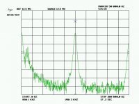
finally the first rev boards have arrived. I started with the DCDC and checked the ripple on the 3.3V supply when resistively loaded with 100mA . here is the spectral plot of the ac voltage on the 3.3V taken from the 2.2u across the 470uF polymer cap.
Attachments
then I added the DSP and other components and keeping a list of fixes to be done for the 2nd rev. I designed a mute circuit using the bitclock as neg rail charge pump to be able to use a NPN transistor. originally I planned a maxim analog switch with neg rail capabilities , but distortion wise the NPN mute seems cleaner and cheaper. the power-on timer does not seem to work as intended. need to work on that.
good news: the XO part operates as planned.
most of the design time goes into the startup and power down glitches
the power-on transients are caused by residual charge on the coupling and filter caps. there is a glitch at 700usec after turn-on when the 3.3Vrail rises above 1V.
I have several options:
- drive the mute directly when raw supply is applied
- use a normally-on device like a Jfet to short the outputs (BF862).
- use a photomos or photo LDR as series element (bulky and expensive)
the neg rail runs off the wordclock charge pump and sits at -3.1V.
- Status
- This old topic is closed. If you want to reopen this topic, contact a moderator using the "Report Post" button.
- Home
- Source & Line
- Digital Line Level
- nanoDSP crossover, suggestions please