one or two things that may be worth checking.
better to switch the coil with positive voltage and keep one side grounded.
the positive side can be bypassed with a cap also to gnd.
that ensure a path towards ground and let the coil act as a shield.
an RF relay, while more expensive, can ensure proper impedance matching.
I confirmed today that the grounding of the coil indeed makes a big difference
")
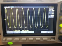
the sine in was 11.29 MHz, 5.5 Vpp
with open relay, on the output I measured:
coil not grounded, 7 mVpp (58 dB isolation)
coil grounded, 0.3 mVpp (84 dB isolation)
Attachments
Nice.
Then, just wanted to signal, that Anders Wallin has an open hardware project of an 8 channel RF mux.
Maybe worth a look. And, for people for ~ABX testing like Doede, could serve as it is!
Projects / RF Multiplexer 8ch 1GHz * Open Hardware Repository
Then, just wanted to signal, that Anders Wallin has an open hardware project of an 8 channel RF mux.
Maybe worth a look. And, for people for ~ABX testing like Doede, could serve as it is!
Projects / RF Multiplexer 8ch 1GHz * Open Hardware Repository
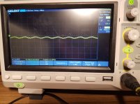
new test,
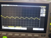
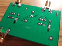
As suggested here, I soldered a 0.1 uF MLCC between coil pin and ground plane at the 3.3V side at each relay and re-measured, and this gave nice results, direct coil grounding not needed anymore I think.
I measured only 0.16 mVpp leakage in the best case.
I changed termination from 100 to 75R (did not have 50R at home at this time) and the waveform looks better. Something that looks like approx 100 MHz is riding on the waveform, picked up from something nearby I guess?
Attachments
new test,
As suggested here, I soldered a 0.1 uF MLCC between coil pin and ground plane at the 3.3V side at each relay and re-measured, and this gave nice results, direct coil grounding not needed anymore I think.
I measured only 0.16 mVpp leakage in the best case.
I changed termination from 100 to 75R (did not have 50R at home at this time) and the waveform looks better. Something that looks like approx 100 MHz is riding on the waveform, picked up from something nearby I guess?
in my experience, one side solidly grounded and the other bypassed by a cap performs best.
By switching the coil "high-side", extra care (filtering) must be taken on the psu that act upon the coils (if shared with other electronics..)
but mileage may vary based upon the type of signal/relay/layout.
Yes, that makes sense.
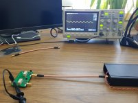
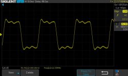
I have tested the switchboard + STS-DX squarer board in my DAC now. Input is Driscoll 11 and 12 MHz + doublers. Sounds good, will make some listening comparisons later when the build is more final.
Output from the squarer mounted in DAC looks like this.
I have tested the switchboard + STS-DX squarer board in my DAC now. Input is Driscoll 11 and 12 MHz + doublers. Sounds good, will make some listening comparisons later when the build is more final.
Output from the squarer mounted in DAC looks like this.
Attachments
I recently received my 5/6mhz Drixo plus doublers to have final 11/12mhz. Powered it with 16V Andrea's TWRPS-pp.
Earlier i had 45/48mhz Crystec 957 and Andrea's Driscoll v1.
To imagine better: jump of sq from Crystec to Driscoll was less prominent, than Driscoll to Drixo.
Most obvious: better resolution with more details and stronger bass. More focus needed: bigger space, fuller sounds extension, less strain, better PRaT. Just less digital, more natural music reproduction.
Im happy Big thanks to Andrea for developing such fine products! It was worth the wait!
Earlier i had 45/48mhz Crystec 957 and Andrea's Driscoll v1.
To imagine better: jump of sq from Crystec to Driscoll was less prominent, than Driscoll to Drixo.
Most obvious: better resolution with more details and stronger bass. More focus needed: bigger space, fuller sounds extension, less strain, better PRaT. Just less digital, more natural music reproduction.
Im happy
Big thanks to Andrea for developing such fine products! It was worth the wait!Note on the TWTMC-DRIXO 5/6 MHz semi-finished boards
5.6448 MHz and 6.144 MHz crystals have very high Q (more than 2M) and high ESR.
We have seen with some crystals that the oscillator needs long time to start and sometimes it doesn't even start.
In this case you can replace R24 (1K) with 1.2K, 1.5K or 1.8K resistor so it will start faster.
The increased value of R24 does not affect the phase noise performance.
Great description. BTW, it gets even better with time. The more focus needed items will become more obvious with time under power.
wlowes,After what duration under power the sound seemed to you stabilize,
with the DRIXO which is impressive it's the feeling of having a higher level of volume,as said Supersurfer no need to mount the potentiometer like before,it's much more dynamic.
clsidxxl.. It is hard to say how long to settle in. I think after 2 weeks it had become stable. It is powered now for almost 2 months. Listening just yesterday it struck me that it seemed the best ever. Normally you make a change, acclimatize and the impact fades. This continues to impress and IMHO the pleasurable aspects continue to improve.
In that time however, I added ReclockPi which had an impact, and then gave ReclockPi a dedicated power supply. This also had an impact. I tend to use capacitors that are notoriously slow to settle, so it's hard to know how much is the evolution due to Drisco settling or these ancillary bits.
In that time however, I added ReclockPi which had an impact, and then gave ReclockPi a dedicated power supply. This also had an impact. I tend to use capacitors that are notoriously slow to settle, so it's hard to know how much is the evolution due to Drisco settling or these ancillary bits.
Fifo lite ?
what are your power Drixo set-up both of you ? Cells ? Regs always switched on from the mains ?
Are there decoupling differences in both of your clock layout ?
Devils are in the details. I.e. and for what it worths, as you are not at iso layouts, I have always suspicion about what one claims as the main enhancement factor.
I have no real doubt about the circa 3 days minima powering on of the crystal -is there a difference if it is cells, super caps, always powered on good regs ?-
Wolwes is making a hard tweak with caps (I'm glad he is using acrylic caps) of all sort (iirc Black Gate that works fine around digital stuffs).
What I mean is the set up are maybe different enough to be prudent about what is causing the enhancement (supercaps as a wall grid electricity stabiliser ?!... that makes the country more equal with the electricity quality provided ?)
That's crazy, as always, as few things can change sota designs with simple things : decoupling, power supplies,etc . I believe it's not always easy to highlight as we have all different layout, and not the less important : the electricity quality that comes out of the walls...
Last edited:
I believe FIFO lite is Andrea's FIFO v1.0 as opposed to 2.0 which will be his no cost barred SOTA attempt. As I understand it, his value proposition for FIFO lite is jitter on all I2S lines close to clock jitter, and separation of Rpi / FIFO to isolate noise. Ian countered with StationPi for isolation in compact form factor and then ReclockPi to preserve clock fidelity across all signals. I can vouch for ReclockPi delivering on it's claim. I soon will put in StationPi and will then report on that. I've reported on my approach to power so I'll leave that to clsidxxl.
The FIFO Lite is here
The Well synchronized asynchronous FIFO buffer - Slaved I2S reclocker
The hardware is ready, but we are still working on the software because it's very complex due to the versatility of the board.
As soon as the software will be ready we need the help of some members who would like to test the first batch of the board with their current DAC.
- Status
- Not open for further replies.
- Home
- Source & Line
- Digital Line Level
- The Well Tempered Master Clock - Building a low phase noise/jitter crystal oscillator