Now this is only brainfarting, but
We have seen that the noise floor halves at each division by 2 of the carrier frequency.
From 11MHz to 176kHz there is an 62.5 division factor.
Let's round it to 64..
If the system would keep the physics all right, then it should show 2^6, that is -36dB difference in the floor, instead of 8dB.. and changing shape..
So there is something which is not perfect.
I expected exactly this reply, now please comment on this plots (I know the reply, but just to confirm ...)
Attachments
Just so as to annoy You, the applied Wilkinson splitter does have a certified lower bandwith at 1MHz.. and already there it's not totally the same as at higher frequencies.
I can understand that it continues to work somehow, but care should be taken.
We have to take the maximum care, since one time there is something which is not perfect (blue line) while another time it works as expected (pink line).
Maybe on odd days there is something wrong ....
Attachments
I have already told my conclusion that the Fifopi seemingly does add a certain floor.
It does not have anything to do with your previous graphs and what I have told for those. I feel it's a bit of shifting the target
Very strange, I don't remember you told that.
Can you quantify how much noise floor is seemingly added?
Anyway I have not changed any parameters /environment, all the last plots have been already published (as an example the last plot was published in post #2433 The Well Tempered Master Clock - Building a low phase noise/jitter crystal oscillator).
No game here, simply measurements (and sometimes unheard suggestions).
Just to clarify once and for all
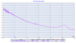
This is the last time we waste time demonstrating what was obvious from the beginning: the Timepod measures correctly the phase noise of square wave clocks, the harmonics of the signal (unlike what someone claims) absolutely don't affect the phase noise analysis as shown below.
We have measured the phase noise of a 5 MHz CMOS output CTS oscillator with and without a low pass filter at 7.5 MHz before the input of the Timepod to suppress the undesired harmonics above its fundamental.
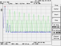
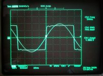
The first picture shows the spectrum analysis of the square wave at 5 MHz without the input filter (green curve) vs the same square wave with the filter at 7.5 MHz (blue line).
As you can see the spectrum of the signal without filter is charged with lot of harmonics, while inserting the low pass filter the harmonics practically disappear.
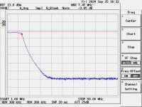
The second picture shows the AC characteristic of the filter we have used.
Finally the third picture shows the phase noise plot comparison between the 5 MHz square wave with (pink line) and without (blues line) the low pass input filter.
As you see the two plots are exactly superimposed, the harmonics of the square wave don't affect the phase noise measurement in the least.
And this was obvious for us since we are measuring the phase noise and not the amplitude noise.
Measuring a 5 MHz square wave its harmonics fall into the passband of the input filter used in the Timepod but the phase noise result is not affected, that demonstrates the reliability of the gear even with square wave clock.
I hope this helps to understand.
This is the last time we waste time demonstrating what was obvious from the beginning: the Timepod measures correctly the phase noise of square wave clocks, the harmonics of the signal (unlike what someone claims) absolutely don't affect the phase noise analysis as shown below.
We have measured the phase noise of a 5 MHz CMOS output CTS oscillator with and without a low pass filter at 7.5 MHz before the input of the Timepod to suppress the undesired harmonics above its fundamental.
The first picture shows the spectrum analysis of the square wave at 5 MHz without the input filter (green curve) vs the same square wave with the filter at 7.5 MHz (blue line).
As you can see the spectrum of the signal without filter is charged with lot of harmonics, while inserting the low pass filter the harmonics practically disappear.
The second picture shows the AC characteristic of the filter we have used.
Finally the third picture shows the phase noise plot comparison between the 5 MHz square wave with (pink line) and without (blues line) the low pass input filter.
As you see the two plots are exactly superimposed, the harmonics of the square wave don't affect the phase noise measurement in the least.
And this was obvious for us since we are measuring the phase noise and not the amplitude noise.
Measuring a 5 MHz square wave its harmonics fall into the passband of the input filter used in the Timepod but the phase noise result is not affected, that demonstrates the reliability of the gear even with square wave clock.
I hope this helps to understand.
Attachments
This is the last time we waste time demonstrating what was obvious from the beginning: the Timepod measures correctly the phase noise of square wave clocks, the harmonics of the signal (unlike what someone claims) absolutely don't affect the phase noise analysis as shown below.
OK, what I have to ask you, while you wrote, low freq. (of master clock) variations is hear able...
Can you post more details about those low freq. variations:
. link or source about
. and may, when or when not it will be hear able as in mHz & Levels
while this relates to the now presented product(s) and measurements...

Hp
I believe it depends on our brain sensitivity to the time errors.
There are a few papers on the web that try to explain the interactions between brain perceptions and time related digital to analog conversion.
There are also some useful posts from Pat Digiacomo on the argument.
When I find the time I will collect these documents and I will publish them.
I cannot mathematically demonstrate the reason why we are so sensitive to the close in phase noise of the master clock, but I believe anyone can empirically experience the result with listening sessions.
It's the case of the FifoPi users who feel huge sound improvements every time they move to a better quality oscillator.
They have reported several times the big sonic improvements when moving from a 50 cents oscillator to the Crystek, and further improvements with a very good oscillator like the Pulsar or my old Driscoll oscillators.
So, what is the difference between a 50 cents oscillator and the Crystek or a better one?
Any decent oscillator has good phase noise at 100 Hz or 1 KHz from the carrier, at least -120/130 dBc, therefore the only difference is the close in phase noise from 10 Hz and below.
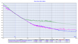
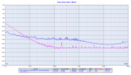
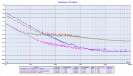
If we assume that the better the quality of the oscillator the better the sonic result (nobody seems to claim the opposite), the attached measurements plot confirms the theory.
Although the noise floor of the FifoPi (30/40 Hz from the carrier and above) is almost the same using whatever oscillator there is a big difference in the close in phase noise (10 Hz from the carrier and below).
IMHO, the better close in phase noise is the reason why we feel such sonic improvements when moving to a better quality oscillator.
There are a few papers on the web that try to explain the interactions between brain perceptions and time related digital to analog conversion.
There are also some useful posts from Pat Digiacomo on the argument.
When I find the time I will collect these documents and I will publish them.
I cannot mathematically demonstrate the reason why we are so sensitive to the close in phase noise of the master clock, but I believe anyone can empirically experience the result with listening sessions.
It's the case of the FifoPi users who feel huge sound improvements every time they move to a better quality oscillator.
They have reported several times the big sonic improvements when moving from a 50 cents oscillator to the Crystek, and further improvements with a very good oscillator like the Pulsar or my old Driscoll oscillators.
So, what is the difference between a 50 cents oscillator and the Crystek or a better one?
Any decent oscillator has good phase noise at 100 Hz or 1 KHz from the carrier, at least -120/130 dBc, therefore the only difference is the close in phase noise from 10 Hz and below.
If we assume that the better the quality of the oscillator the better the sonic result (nobody seems to claim the opposite), the attached measurements plot confirms the theory.
Although the noise floor of the FifoPi (30/40 Hz from the carrier and above) is almost the same using whatever oscillator there is a big difference in the close in phase noise (10 Hz from the carrier and below).
IMHO, the better close in phase noise is the reason why we feel such sonic improvements when moving to a better quality oscillator.
Attachments
. and may, when or when not it will be hear able as in mHz & Levels
while this relates to the now presented product(s) and measurements...
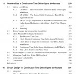
Attached below is part of the Table of Contents from the book, Understanding Delta-Sigma Data Converters, 2nd Ed. As can be seen, a fair amount of attention is given to phase noise. If you take a look at the book you may find that the relationship between phase noise and data converter errors is quite complex.
Attachments
Last edited:
I believe it depends on our brain sensitivity to the time errors.
There are a few papers on the web that try to explain the interactions between brain perceptions and time related digital to analog conversion.
There are also some useful posts from Pat Digiacomo on the argument.
When I find the time I will collect these documents and I will publish them.
Yes please...
Attached below is part of the Table of Contents from the book, Understanding Delta-Sigma Data Converters, 2nd Ed. As can be seen, a fair amount of attention is given to phase noise. If you take a look at the book you may find that the relationship between phase noise and data converter errors is quite complex.
The beef question is, are they taking about the beef or providing real HW beefy information
Andrea,
I suggest an additional module: Mixer & filter of two low PN oscillators, one apart as 1 / 10 / 12 kHz, so we have a low PN 1 / 10 / 12kHz audio generator for ADC PN / Jitter measuring. As soon you would like to check the ADC at an 10/12kHz signal, the DAC solution would add to much PN/Jitter as a reference do the various PN/Jitter contribution
Mixer & Filter Box with SMA connector for the various low PN oscillators. May based at 5.0 or 10.0 Mhz with lowest possible PN.
Currently, I am at this point now
Hp
Problem is that it is hard to pull a low PN oscillator more than some Hz..
One should ask a specific run with these crystals..
Than.. The usual level for mixers is like 7dBm, (~500mVrms), 10/13dBm (~1Vrms) and, maybe, 17dBm (1,5V rms)..
And that is before the mixer, so should calculate insertion loss.
How much is the ADC max input? One would need full scale excitation, me thinks.
Interesting idea, anyway
Last edited:
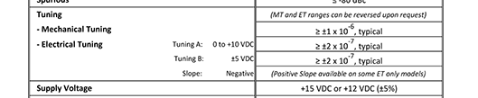
The idea sounded interesting until I checked. I have 2 5 MHz Wenzel Streamlines coming for references. I checked the specs (below) and I could get maybe 10 Hz between them MAX. Not that useful.
However I have a modified Ballantine Time mark generator for scope calibration (I had to do some tweaking to get some hum modulation out of it) but its a synchronous counter and I really did not get any discernable jitter with it and the AK5394A demo board + quality reference oscillator. I'll dig it all out and check it with the RTX to see what I get but I have not seen evidence of jitter on the ADC side once the clocks are OK. I can run it from an external clock so it can be tuned to 12 KHz I think. It will be interesting.
However I have a modified Ballantine Time mark generator for scope calibration (I had to do some tweaking to get some hum modulation out of it) but its a synchronous counter and I really did not get any discernable jitter with it and the AK5394A demo board + quality reference oscillator. I'll dig it all out and check it with the RTX to see what I get but I have not seen evidence of jitter on the ADC side once the clocks are OK. I can run it from an external clock so it can be tuned to 12 KHz I think. It will be interesting.
Attachments
Hm.. Effectively, it would be enough to special order a
5,01 MHz crystal from Laptech, min quota, and use it coupled to some classic 5MHz oscillator..
But I'm afraid that some low noise/ phase noise amp would still be needed after the mixer for proper signal level.
5,01 MHz crystal from Laptech, min quota, and use it coupled to some classic 5MHz oscillator..
But I'm afraid that some low noise/ phase noise amp would still be needed after the mixer for proper signal level.
Last edited:
Andrea,
I suggest an additional module: Mixer & filter of two low PN oscillators, one apart as 1 / 10 / 12 kHz, so we have a low PN 1 / 10 / 12kHz audio generator for ADC PN / Jitter measuring. As soon you would like to check the ADC at an 10/12kHz signal, the DAC solution would add to much PN/Jitter as a reference do the various PN/Jitter contribution
Mixer & Filter Box with SMA connector for the various low PN oscillators. May based at 5.0 or 10.0 Mhz with lowest possible PN.
Currently, I am at this point now
Hp
I don't know the context of this post, so maybe what I'm about to write makes no sense, but if you want 1 kHz with low close-in phase noise, why not use a crystal oscillator and a frequency divider? For close-in phase noise, you'll gain 20 dB*log10(N) then when dividing by N. (For the noise floor, you only gain 10 dB*log10(N) and you get extra noise from the divider itself.) If you want something sinewave-like, you can still put an LC low-pass filter after the frequency divider.
Last edited:
- Status
- Not open for further replies.
- Home
- Source & Line
- Digital Line Level
- The Well Tempered Master Clock - Building a low phase noise/jitter crystal oscillator