Boards 3D model
Since a member asks for boards 3D model I publish 3D PDF document for each boards mentioned in this thread.
View attachment TWTMC-C.PDF
View attachment TWTMC-D.pdf
View attachment TWTMC-DIL.PDF
View attachment TWTMC-OVN.PDF
View attachment TWTMC-P.pdf
View attachment TWRPS-pp micro.PDF
Since a member asks for boards 3D model I publish 3D PDF document for each boards mentioned in this thread.
View attachment TWTMC-C.PDF
View attachment TWTMC-D.pdf
View attachment TWTMC-DIL.PDF
View attachment TWTMC-OVN.PDF
View attachment TWTMC-P.pdf
View attachment TWRPS-pp micro.PDF
In an ideal world you would test each crystal for its "turnover" temp, the temperature at which its most stable and then adjust the heater to match usually within +/- .1C or whatever you can manage. In that case each crystal will be a little different.
I don't think that's possible with this type of oven and you aren't chasing frequency perfection, just stability, low drift and low phase noise so probably no real sacrifice to share an oven.
I don't think that's possible with this type of oven and you aren't chasing frequency perfection, just stability, low drift and low phase noise so probably no real sacrifice to share an oven.
In an ideal world you would test each crystal for its "turnover" temp, the temperature at which its most stable and then adjust the heater to match usually within +/- .1C or whatever you can manage. In that case each crystal will be a little different.
That's what they do in commercial double crystal ovens:
< http://www.karlquist.com/oven.pdf >
He talks about crystal temperature stability of +- 100 uK (Mikro-Kelvin).
You don't know the exact inflection point of your crystals, just
that ist's somewhere near 70°C or whatever you have ordered, and you
have no realistic means to measure it.
But that's not really bad. The simple oven will allow your crystal to
operate close to the sweet spot. Remember other crystals have to work
without any temp stabilization. I would not hesitate to put 2 crystals
into the same oven, as long as they are designed for the same temperature.
Just make sure that they cannot see each other electrically.
regards, Gerhard
Many thanks for your replies, gentlemen!
The crystals are sitting tightly in the copper tube, so their housings will be connected electrically together. Is that an issue? Do I have to try to find away to isolate the housings from each other?
Regarding the temperature setting points, I do not have the exact measurement data from the manufacturer and which working temperatures are recommended for my crystals. (Maybe Andrea could help on that topic if he still has the manufacturer data). What I did was to choose the temperature of 82°C mentioned in the Andreas's document as the starting point and then fine adjusted it just by hearing! The sound changes are audible within few centigrade ( 3°C ?), so I hope that the recommended temperatures for the two crystals are within few centigrade too.")
what is your experiences for adjusting the temperature of the oven ? Do you hear changes in sound quality , let's say, for +/- 1°C?
Best regards
The crystals are sitting tightly in the copper tube, so their housings will be connected electrically together. Is that an issue? Do I have to try to find away to isolate the housings from each other?
Regarding the temperature setting points, I do not have the exact measurement data from the manufacturer and which working temperatures are recommended for my crystals. (Maybe Andrea could help on that topic if he still has the manufacturer data). What I did was to choose the temperature of 82°C mentioned in the Andreas's document as the starting point and then fine adjusted it just by hearing! The sound changes are audible within few centigrade ( 3°C ?), so I hope that the recommended temperatures for the two crystals are within few centigrade too.
what is your experiences for adjusting the temperature of the oven ? Do you hear changes in sound quality , let's say, for +/- 1°C?
Best regards
I'm not home at the moment but Andrea posted the shipping docs and they do contain the temps. Here is the list from the latest batch: The Well Tempered Master Clock - Group buy
Greetings,
I please have some questions, I think I missunderstood several things.
Does the temperature of the dac cabinet can change the temperature targett of the ovens?
I think I easily have around 35c inside the cabinet ...
What about the distance between an oscillator/sc cut crystal with a masterclockboard (ianfifo in my setup)? If there are for example 4 inches, will it add jitter? If yes is it that important for a 16/44 or 20/96 old pcm dac chip ?
Is there a problem of frequency or stability of it with extra jitter due to the distance?
Does it affect phase noise which seems from the few I believe to understand is what we want at low frequencies below 10 htz vs cchd-957 or NDK crystals?
Many questions sorry, I get the 5 Mhz sc cut from Andrea and I would like to know the best layout trade off I should targett but some basics I already understood as the wire impedance between boards.
Many thanks if you can enlight me,
Regards
I thought the temp listed on the crystal case was supposed to be the inflection point temp?
oh yes, you are right. many thanks!
Greetings,
I please have some questions, I think I missunderstood several things.
Does the temperature of the dac cabinet can change the temperature targett of the ovens?
I think I easily have around 35c inside the cabinet ......
Many thanks if you can enlight me,
Regards
Great questions.
I have exactly the same question about the temperature changes. How much does the performace of the ovenclock change if the tempature is raised or lowered by for example 10 or 15 degrees celsius? Is it then still better then the CCHD957 or is it worse in such scenario? Any feedback is welcome, many thanks for this great project
Hi Andrea,
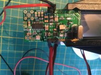
I have build my first driscoll clock unit with a 45.1584mhz sc-cut crystal.
The build is fine as far as I can judge. Smd soldering is not too bad if the right tools are used, soldering paste works very good.
The only thing is that there were two parts that mouser did not have in stock, I started out with an alternative:
L4 should be 1,5uH, I used 1,8uH (also have 1,2uH in stock)
Q1 should be NE85633, I used MMBT5179 but I do not know how to select for high hfe.
The clock is not working on Ians fifopi.
Do you have any suggestions?
Or maybe an adress where I can get the correct parts (for a reasonable price).
Regards,
Attachments
The clock is not working on Ians fifopi.
Do you have any suggestions?
Or maybe an adress where I can get the correct parts (for a reasonable price).
Regards,
Do you have an oscilloscope to measure the output? I got 24.576Mhz working, but the 49M never worked. I suspect the 45M will do the same. At my best, it only outputs 16.x Mhz. The parts here are very sensitive.
Hi Andrea,
I have build my first driscoll clock unit with a 45.1584mhz sc-cut crystal.
The build is fine as far as I can judge. Smd soldering is not too bad if the right tools are used, soldering paste works very good.
The only thing is that there were two parts that mouser did not have in stock, I started out with an alternative:
L4 should be 1,5uH, I used 1,8uH (also have 1,2uH in stock)
Q1 should be NE85633, I used MMBT5179 but I do not know how to select for high hfe.
The clock is not working on Ians fifopi.
Do you have any suggestions?
Or maybe an adress where I can get the correct parts (for a reasonable price).
Regards,
Hi,
L4 is a critical part since it's used to tune the oscillator at the crystal frequency, so you should use exactly the value indicated in the BOM. It seems that Mouser has the part in stock ILSB1206ER1R5K Vishay / Dale | Mouser Europe
To select the hfe of the MMBT5179 you need a DMM that implements this function. Anyway the oscillator should work properly with the MMBT5179 without any selection of the part.
Finally, you need an oscilloscope to see the output of the oscillator if it does not work correctly.
Please, remember to set the bias of the bjt by trimming R11, as in the assembly guide at page 18.
Andrea
P.S. You can source the NE85633 here: NE85633 (2SC3356) NEC | Silicon bipolar NPN RF transistor, SOT-23 | Buy on-line | rf-microwave.com
Last edited:
Hi,
L4 is a critical part since it's used to tune the oscillator at the crystal frequency, so you should use exactly the value indicated in the BOM. It seems that Mouser has the part in stock ILSB1206ER1R5K Vishay / Dale | Mouser Europe
To select the hfe of the MMBT5179 you need a DMM that implements this function. Anyway the oscillator should work properly with the MMBT5179 without any selection of the part.
Finally, you need an oscilloscope to see the output of the oscillator if it does not work correctly.
Please, remember to set the bias of the bjt by trimming R11, as in the assembly guide at page 18.
Andrea
P.S. You can source the NE85633 here: NE85633 (2SC3356) NEC | Silicon bipolar NPN RF transistor, SOT-23 | Buy on-line | rf-microwave.com
Hi Andrea, (and Canvas),
Thanks for your assistance.
I have an old tektronix 335 scope that goes to 35MHz (and an old Philips tube scope on 10MHz) this will not be of any use for these problems.
The bias of the bjt is set as described.
I will get the correct L4, it is in stock now at mouser but was out of stock when I purchased the components. If I understand you correctly the transistor will be ok so I will leave it for now and see if it works with the right L4 value.
Regards,
Last edited:
Hi Supersurfer,
Cheers,
Jesper
... supposing this is an analogue scope I reckon you would get some indication of what is going on even if it is slightly outside of the scope's nominal frequency range ... And, although you may know about this, the cables also has quite some influence so setting the cable to the x10 range may cause less influence/attenuation of the signal measured.I have an old tektronix 335 scope that goes to 35MHz
Cheers,
Jesper
Hi Supersurfer,
... supposing this is an analogue scope I reckon you would get some indication of what is going on even if it is slightly outside of the scope's nominal frequency range ... And, although you may know about this, the cables also has quite some influence so setting the cable to the x10 range may cause less influence/attenuation of the signal measured.
Cheers,
Jesper
Hi Jesper,
Thanks for your suggestion. I will give it a try!
Regards,
Hi,
L4 is a critical part since it's used to tune the oscillator at the crystal frequency, so you should use exactly the value indicated in the BOM.
Yes!
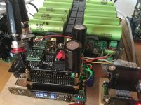
I got the 1,5uH from mouser today and the clock is working now.
I did not check the signal with a scope but it is playing music on my fifopi currently!
Now its time to let it run in for a while.
Regards,
Attachments
- Status
- Not open for further replies.
- Home
- Source & Line
- Digital Line Level
- The Well Tempered Master Clock - Building a low phase noise/jitter crystal oscillator