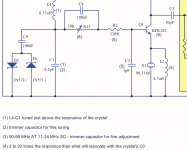
I don't have much time now, but in the Driscoll I spotted this:
The inductor in parallel to the crystal should resonate with C0 and not be much larger. This is not a choke but the intent is to remove C0. At high frequencies, a large C0 might present a capacitance that makes it impossible to reach a purely real impedance on the crystal series resonance, but this is required.
The oscillation happens on the frequency where the phase of the loop gain goes through 0. And the delay through the loop has to be adjusted that at this passage through 0 the phase slope is maximum steep. That can be optimized by the resonance frequency of the feedback network.
Remember that at the -3 dB points of a filter, the phase shift is +/-45°, so you have maybe 70° of space for adjustment. (unless you do non-minimum-phase nasties).
dPhase / dFrequency is another expression for the working Q. Working Q is always smaller than the pure crystal Q, so it is important that the max. of that what is left over happens on the oscillation frequency and not 10 KHz off.
Also, I do not think that insufficient gain is a problem, as mentioned sometimes above. Any low cost RF transistor should be able to deliver 20 dB at 100 MHz, more than needed.
---
This text here has appeared in print in "Dubus Technical Book 5". It is not the final thing since the Pagemaker files have been lost; it is from the Word files I sent to the editor as original input. It is about a Butler oscillator, but the loop gain principle is universal.
Also, my address given there is no longer valid. The content is both German & English since DUBUS works that way. When I find a suitable scanner driver and the time to install it, I may scan the final text. But it will be B/W only because of the print.
< http://www.hoffmann-hochfrequenz.de/downloads/Hoffmann_VHF_Quarzoszillatoren_Teil1.pdf >
< http://www.hoffmann-hochfrequenz.de/downloads/Hoffmann_VHF_Quarzoszillatoren_Teil2.pdf >
cheers, Gerhard
Attachments
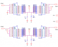
Hi. In the DIL pdf., option 3 for connecting boards describes cutting up 2 daughterboards to have 4 independent supplies for the oscillators.
Since there is no scoring on the daughterboard, and a number or pads/holes would appear to get ruined during cutting, I'm curious if this is really possible and if so, what the recommended procedure is.
TIA
Since there is no scoring on the daughterboard, and a number or pads/holes would appear to get ruined during cutting, I'm curious if this is really possible and if so, what the recommended procedure is.
TIA
Hi,
work in progress…. it's a complex project that takes long time. I will share all as soon as a prototype is ready and sounding.
Andrea
Hi Andrea
I made one deskret 1bit circuit (for DSD at the start...), based on the chat among You and EC Design and folks at the other topic (TDA1541A dac).
.
In practice it is working, and with very good sonic results. It is about 3state logic output. I made balanced like in the sch for driving interstage transformer. to be as simpoe as could be for the test strat and to avoid DC offset at the output ov each line.
.
Now I will try to extend for R2R 24bit, only it deseves 24 x 4 ICs x 2 for stereo

cheers
Attachments
I just came across this thread and it is impressive! Adrea and many others have done an amazing job. I have done my best to read through the 171 pages (whew!) and I would like to try the Driscoll design using a SC cut crystal if possible.
I see the parts that are necessary for a 11.2896 MHz signal. For a 12MHz signal (what I need) do I just vary C1 and/or C3 to get 12MHz?
I need a CMOS output - am I right that the board design allows this?
It looks like getting the correct Laptech HC43/U crystal is difficult unless there are any left over from the group buy?
Last edited:
Hi Andrea
I made one deskret 1bit circuit (for DSD at the start...), based on the chat among You and EC Design and folks at the other topic (TDA1541A dac).
.
In practice it is working, and with very good sonic results. It is about 3state logic output. I made balanced like in the sch for driving interstage transformer. to be as simpoe as could be for the test strat and to avoid DC offset at the output ov each line.
.
Now I will try to extend for R2R 24bit, only it deseves 24 x 4 ICs x 2 for stereo
cheers
Hi Zoran,
great news! I believe this is the right way to get a great sounding DAC.
My approach is similar, you are using a differential DAC while I'm using 2 x 23 bit DAC, one for the positive rail and the other for the negative one.
I'm thinking to use single flip-flop for each bit, so I need more ICs than you, also because I use a mixed ladder network, the first 5 MSBs are thermometer decoded (1 to 31). A lot of parts!
Have you implemented a FIFO in the CPLD?
Andrea
Hi Andrea
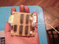
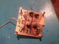
I just made a stereo 1bit ballanced discrete dac for DSD. Just to see if it is working or not. And with simple parts from local store DIP packages, for point to point tryout... I didn't implement any logic like shift register or something in this example. I also tried couple of interstage transformers for Bal to SE mode (WE, Picatron etc) and find that Beyer Dynamics are somehow best sounding in this application. I use Amanero DSD output (isolated) and straight to this circuit. Just one HC74 to "recklock" and get + and - DATA DSD lines. The simple starting measurements was dificult because I have to use some hardware converter from I2S PCM stream generating by software (Fuzzmeasure), but I get it somehow... Mainly to adopt interstage for optimum load, ringing and BW.
The Generator internal resistance of this circuit is low because it is dividing by 8 times serial R at each Driver inside the HC540. And leading to lower value of Riv. So the driving complicated interstages are not the issue. I put JFET buffer after the interstage transformer, to keep the konstant impedance loading at the secondary and to lower output impedance of the device (that plate, PS and USB interface are not at the picture)
.
This is my third experimental piece, I solder before one I2S 32bit latch, 16 to 32 bit ladder R2R clasic, and one 32bit DSD dac. And I can say that these "worst case scenario" experimental devices are not bad at all.
.
I think that You will have better results using single FF for each bit hift register than classic 164 or 594/5, and it is the way to get differential DATA lines in the same time?
.
Consider some 32bit FIFO shift register?
I thin that CPLDs and other programmable ICs are good, at least for saving the space, but that may be little bit "unpure" for discrete concept. ha ha.
.
cheers (and thanks for notice, I post the same on the some other topics and it was without any response...)
Attachments
Hi folks,
It's an astounding thread.
Need a little help with my Driscoll oscillator.
I am experimenting with an SC cut crystal, from the datasheet:
freq. 5MHz, 3rd ovt., C0 2.5pF max, C1 0.14fF, DL 0.01-0.1mW, ESR 130R,
Q 1.6M
For Q1 I'm using the MMBT5179, 120R for R1, 1mH for L2,
C1 24pF, L4 33uH,
C2 75pF
Voltage readings around Q1:
Vcc: +6.27V
emitter: 351mV
base: 1.137V
collector: 3.18V
so it is drawing around 26.5mA
I have no oscillation at all, measuring at the output (c5, 10p).
What has gone wrong? Any suggestion?
Thank you in advance.
It's an astounding thread.
Need a little help with my Driscoll oscillator.
I am experimenting with an SC cut crystal, from the datasheet:
freq. 5MHz, 3rd ovt., C0 2.5pF max, C1 0.14fF, DL 0.01-0.1mW, ESR 130R,
Q 1.6M
For Q1 I'm using the MMBT5179, 120R for R1, 1mH for L2,
C1 24pF, L4 33uH,
C2 75pF
Voltage readings around Q1:
Vcc: +6.27V
emitter: 351mV
base: 1.137V
collector: 3.18V
so it is drawing around 26.5mA
I have no oscillation at all, measuring at the output (c5, 10p).
What has gone wrong?
Any suggestion?Thank you in advance.
I have not yet tried any SC-Cut crystal at 5MHz, but it seems that R1 is a bit low.
You could try using the following values:
R1 around 1K2 (1K to 1K2)
L4 33uH
L1 1mH
R2 180R
R11 100K trimmer
C1 around 20pF
C2 18pF
C3 18pF
Then, if it oscillates at B-mode (around 5.5MHz) you could replace C3 with 12pF and C1 with a capacitor plus an inductor in series: 18pF and 33uH.
Please, let us know.
Hi Andrea, Thanks for your reply. It seems all is working fine with the values you suggested, it's interesting to note that at Vcc/2 on the collector, oscillation fails to start, in my case, it reads a bit less, and oscillation starts in 6.3 seconds on average, at exactly 5.0000MHz! I'm using a standard option PotSemi as squarer, all seems fine.
These are the new voltage readings around Q1:
Vcc: 6.05V emitter 50mV base: 0.8V collector: 2.339V
Output clock appears to be very stable, however I still have to mount the proper oven, so I'm expecting results will be even improved. I bought the quartz from an Israeli dist., it's in a TO-8 case, I guess is made by Nofech, but I'm not 100% sure. On it's case, a small handwritten text is readable, saying 91.2°C, I will try with the oven set at the suggested temp.
I wish I could measure the actual PN, but I'm a newbie and not sure how to make proper measurement. I got very recently an SSA3021x, but still learning it's use.
Thank you so much.
Hi,
glad to know all is working with the new values.
If the crystal comes from Israel I'm enough sure that it's a Nofech production, the build very very good crystals!
About the phase noise measurement I'm note sure you can perform the test with your spectrum analyzer. You should analyze the phase noise at 10 or 1Hz from the carrier and your oscillator, with such that crystal, could measures far better than the noise of your SA.
Andrea
Does anyone have an opinion on this circuit?
Discrete Low Jitter Clock GB
Discrete Low Jitter Clock GB
The schematic is in the pdf at top of page.

I like the differential factor of it due to the increased PSRR.
I've been trying to make a driscol circuit differential without too much luck. I'm not very good at these types of circuits, I've never made an XO before.

I'm wondering how differential use affects Q factor as well.
I like the differential factor of it due to the increased PSRR.
I've been trying to make a driscol circuit differential without too much luck. I'm not very good at these types of circuits, I've never made an XO before.
I'm wondering how differential use affects Q factor as well.
Attachments
Last edited:
How does one order an SC cut crystal? They don't seem to be easy to come by.
I'm assuming they are expensive? Since they appear to only be custom orderable?
Also has anyone yet determined which of the circuits proposed here is best?
Hi,
you can find some comparison here:
The Well Tempered Master Clock - Building a low phase noise/jitter crystal oscillator
The Well Tempered Master Clock - Building a low phase noise/jitter crystal oscillator
The Well Tempered Master Clock - Building a low phase noise/jitter crystal oscillator
Andrea
I don't think so, I have measured the oscillator of the original schematic, you can find the result here:
Discrete Low Jitter Clock GB
Discrete Low Jitter Clock GB
- Status
- Not open for further replies.
- Home
- Source & Line
- Digital Line Level
- The Well Tempered Master Clock - Building a low phase noise/jitter crystal oscillator