- andrea_mori : 2 x 5.6448MHz + 2 x 11.2896MHz + 1 X 22.5792 MHz + 1 x 24.576 MHz + 1 x 45.1584 MHz + 1 x 49.152 MHz + 10 x PCB + 4 x daughter board PCB
- Eldam : 1 x 11.2896 Mhz + 4 x PCB
- esgigt : 1 x 11.2896 Mhz + 1 x PCB, soldered if possible
- fralippo : 1 x 22.5792 MHz and 1 x 24.576 MHz + 2 x PCB
- mravinsky : 2 x 11.2896 Mhz + 1 x PCB
- TNT : 1x22.5792MHz 1x24.5760MHz + 2 x PCB, soldered if possible
- 1audio : 1x22.5792MHz 1x24.5760MHz + 2 x PCB
- randytsuch : 2x25.0000MHz + 4 x PCB
- TNT or maybe : 1 x 11.2896 Mhz + 1 x PCB, soldered if possible
- myint67 : 1x11.2896mhz + 1pcb also soldered if possible
- EdwardTam : 2x 16.9344MHz + 1x PCB
- BDL : 1 x 11.2896 MHz + 2 x PCB
- thorstenlarsen : 2 x 11.2896 MHz + 2 x PCB
- Zoran : 1x22.5792MHz 1x24.5760MHz + 2 x PCB, (soldered or not...)
- walangalam : 1 x 11.2896 Mhz + 2 x PCB
- AR2: 1 x 22.5792 MHz and 1 x 24.576 MHz + 2 x PCB (soldering not needed)
- mcluxun: 1 x 22.5792 MHz and 1 x 24.576 MHz + 2 x PCB (soldering not needed)
- damohpi: 1 x 11.2896 + 1x PCB unsoldered
- noizas : 2 x 5.6448MHz + 2 x 11.2896MHz + 4 x PCB
- badrisuper : : 1 x 11.2896 Mhz + 2 x PCB
- Clsidxxl: 1 x 45.1584 MHz + 1 x 49.152 MHz + 2 x PCB (soldering if possible)
Cost?
//
Please, see post #36 and #48 for the cost estimation.
As soon as the list will be closed, I will ask for the final cost depending on the quantity.
list
- zeta4 1x 22.5792Mhz + 1 x PCB (soldering not needed)- andrea_mori : 2 x 5.6448MHz + 2 x 11.2896MHz + 1 X 22.5792 MHz + 1 x 24.576 MHz + 1 x 45.1584 MHz + 1 x 49.152 MHz + 10 x PCB + 4 x daughter board PCB
- Eldam : 1 x 11.2896 Mhz + 4 x PCB
- esgigt : 1 x 11.2896 Mhz + 1 x PCB, soldered if possible
- fralippo : 1 x 22.5792 MHz and 1 x 24.576 MHz + 2 x PCB
- mravinsky : 2 x 11.2896 Mhz + 1 x PCB
- TNT : 1x22.5792MHz 1x24.5760MHz + 2 x PCB, soldered if possible
- 1audio : 1x22.5792MHz 1x24.5760MHz + 2 x PCB
- randytsuch : 2x25.0000MHz + 4 x PCB
- TNT or maybe : 1 x 11.2896 Mhz + 1 x PCB, soldered if possible
- myint67 : 1x11.2896mhz + 1pcb also soldered if possible
- EdwardTam : 2x 16.9344MHz + 1x PCB
- BDL : 1 x 11.2896 MHz + 2 x PCB
- thorstenlarsen : 2 x 11.2896 MHz + 2 x PCB
- Zoran : 1x22.5792MHz 1x24.5760MHz + 2 x PCB, (soldered or not...)
- walangalam : 1 x 11.2896 Mhz + 2 x PCB
- AR2: 1 x 22.5792 MHz and 1 x 24.576 MHz + 2 x PCB (soldering not needed)
- mcluxun: 1 x 22.5792 MHz and 1 x 24.576 MHz + 2 x PCB (soldering not needed)
- damohpi: 1 x 11.2896 + 1x PCB unsoldered
- noizas : 2 x 5.6448MHz + 2 x 11.2896MHz + 4 x PCB
- badrisuper : : 1 x 11.2896 Mhz + 2 x PCB
- Clsidxxl: 1 x 45.1584 MHz + 1 x 49.152 MHz + 2 x PCB (soldering if possible)
- andrea_mori : 2 x 5.6448MHz + 2 x 11.2896MHz + 1 X 22.5792 MHz + 1 x 24.576 MHz + 1 x 45.1584 MHz + 1 x 49.152 MHz + 10 x PCB + 4 x daughter board PCB
- Eldam : 1 x 11.2896 Mhz + 4 x PCB
- esgigt : 1 x 11.2896 Mhz + 1 x PCB, soldered if possible
- fralippo : 1 x 22.5792 MHz and 1 x 24.576 MHz + 2 x PCB
- mravinsky : 2 x 11.2896 Mhz + 1 x PCB
- TNT : 1x22.5792MHz 1x24.5760MHz + 2 x PCB, soldered if possible
- 1audio : 1x22.5792MHz 1x24.5760MHz + 2 x PCB
- randytsuch : 2x25.0000MHz + 4 x PCB
- TNT or maybe : 1 x 11.2896 Mhz + 1 x PCB, soldered if possible
- myint67 : 1x11.2896mhz + 1pcb also soldered if possible
- EdwardTam : 2x 16.9344MHz + 1x PCB
- BDL : 1 x 11.2896 MHz + 2 x PCB
- thorstenlarsen : 2 x 11.2896 MHz + 2 x PCB
- Zoran : 1x22.5792MHz 1x24.5760MHz + 2 x PCB, (soldered or not...)
- walangalam : 1 x 11.2896 Mhz + 2 x PCB
- AR2: 1 x 22.5792 MHz and 1 x 24.576 MHz + 2 x PCB (soldering not needed)
- mcluxun: 1 x 22.5792 MHz and 1 x 24.576 MHz 1 x 45.1584 MHz + 1 x 49.152 MHz+ 2 x PCB (soldering if possible)
- damohpi: 1 x 11.2896 + 1x PCB unsoldered
- noizas : 2 x 5.6448MHz + 2 x 11.2896MHz + 4 x PCB
- badrisuper : : 1 x 11.2896 Mhz + 2 x PCB
- Clsidxxl: 1 x 45.1584 MHz + 1 x 49.152 MHz + 2 x PCB (soldering if possible)
- zeta4 1x 22.5792Mhz + 1 x PCB (soldering not needed)
updated mine
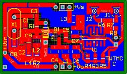
Updated PCB
This is the updated PCB layout, compliant with overtone crystals.
Attached also the updated schematic and parts list.
I'm working on daughter board PCB, including Demian's power supply.
If someone was interested on daughter board, please add to the list.
This is the updated PCB layout, compliant with overtone crystals.
Attached also the updated schematic and parts list.
I'm working on daughter board PCB, including Demian's power supply.
If someone was interested on daughter board, please add to the list.
Attachments
- andrea_mori : 2 x 5.6448MHz + 2 x 11.2896MHz + 1 X 22.5792 MHz + 1 x 24.576 MHz + 1 x 45.1584 MHz + 1 x 49.152 MHz + 10 x PCB + 4 x daughter board PCB
- Eldam : 1 x 11.2896 Mhz + 4 x PCB
- esgigt : 1 x 11.2896 Mhz + 1 x PCB, soldered if possible
- fralippo : 1 x 22.5792 MHz and 1 x 24.576 MHz + 2 x PCB + 1 x daughter board PCB
- mravinsky : 2 x 11.2896 Mhz + 1 x PCB
- TNT : 1x22.5792MHz 1x24.5760MHz + 2 x PCB, soldered if possible
- 1audio : 1x22.5792MHz 1x24.5760MHz + 2 x PCB
- randytsuch : 2x25.0000MHz + 4 x PCB
- TNT or maybe : 1 x 11.2896 Mhz + 1 x PCB, soldered if possible
- myint67 : 1x11.2896mhz + 1pcb also soldered if possible
- EdwardTam : 2x 16.9344MHz + 1x PCB
- BDL : 1 x 11.2896 MHz + 2 x PCB
- thorstenlarsen : 2 x 11.2896 MHz + 2 x PCB
- Zoran : 1x22.5792MHz 1x24.5760MHz + 2 x PCB, (soldered or not...)
- walangalam : 1 x 11.2896 Mhz + 2 x PCB
- AR2: 1 x 22.5792 MHz and 1 x 24.576 MHz + 2 x PCB (soldering not needed)
- mcluxun: 1 x 22.5792 MHz and 1 x 24.576 MHz 1 x 45.1584 MHz + 1 x 49.152 MHz+ 2 x PCB (soldering if possible)
- damohpi: 1 x 11.2896 + 1x PCB unsoldered
- noizas : 2 x 5.6448MHz + 2 x 11.2896MHz + 4 x PCB
- badrisuper : : 1 x 11.2896 Mhz + 2 x PCB
- Clsidxxl: 1 x 45.1584 MHz + 1 x 49.152 MHz + 2 x PCB (soldering if possible)
- zeta4 1x 22.5792Mhz + 1 x PCB (soldering not needed)
daughter board PCB added.
Added daughter boards and more Xtals. I will probably end up building a phase noise test set out of this stuff. To that end I will be using varactor diodes in series with the crystals to be able to tune them.- andrea_mori : 2 x 5.6448MHz + 2 x 11.2896MHz + 1 X 22.5792 MHz + 1 x 24.576 MHz + 1 x 45.1584 MHz + 1 x 49.152 MHz + 10 x PCB + 4 x daughter board PCB
- Eldam : 1 x 11.2896 Mhz + 4 x PCB
- esgigt : 1 x 11.2896 Mhz + 1 x PCB, soldered if possible
- fralippo : 1 x 22.5792 MHz and 1 x 24.576 MHz + 2 x PCB + 1 x daughter board PCB
- mravinsky : 2 x 11.2896 Mhz + 1 x PCB
- TNT : 1x22.5792MHz 1x24.5760MHz + 2 x PCB, soldered if possible
- 1audio : 2x22.5792MHz 2x24.5760MHz + 2 x PCB + daughter board.
- randytsuch : 2x25.0000MHz + 4 x PCB
- TNT or maybe : 1 x 11.2896 Mhz + 1 x PCB, soldered if possible
- myint67 : 1x11.2896mhz + 1pcb also soldered if possible
- EdwardTam : 2x 16.9344MHz + 1x PCB
- BDL : 1 x 11.2896 MHz + 2 x PCB
- thorstenlarsen : 2 x 11.2896 MHz + 2 x PCB
- Zoran : 1x22.5792MHz 1x24.5760MHz + 2 x PCB, (soldered or not...)
- walangalam : 1 x 11.2896 Mhz + 2 x PCB
- AR2: 1 x 22.5792 MHz and 1 x 24.576 MHz + 2 x PCB (soldering not needed)
- mcluxun: 1 x 22.5792 MHz and 1 x 24.576 MHz 1 x 45.1584 MHz + 1 x 49.152 MHz+ 2 x PCB (soldering if possible)
- damohpi: 1 x 11.2896 + 1x PCB unsoldered
- noizas : 2 x 5.6448MHz + 2 x 11.2896MHz + 4 x PCB
- badrisuper : : 1 x 11.2896 Mhz + 2 x PCB
- Clsidxxl: 1 x 45.1584 MHz + 1 x 49.152 MHz + 2 x PCB (soldering if possible)
- zeta4 1x 22.5792Mhz + 1 x PCB (soldering not needed)
daughter board PCB added.
Colleagues how to be with others. System will have to be powered by batteries. Inverter current - voltage is also questionable. Next need a low-noise amplifier before. This question should be addressed comprehensively. Regards.
Me too, I don't understand the question about such that amplifier.
About power supply, the only benefit using batteries is better isolation from main AC (read stray capacitance of the transformer). For the rest, batteries are noisy, noisier than the regulators. In any case the regulators are essential, also using batteries.
But since the regulators need around 18 VDC at the input, everyone is free to use batteries in place of transformer, rectifiers and filtering. In that case I suggest to use strong LC filtering after batteries to reduce the noise.
- andrea_mori : 2 x 5.6448MHz + 2 x 11.2896MHz + 1 X 22.5792 MHz + 1 x 24.576 MHz + 1 x 45.1584 MHz + 1 x 49.152 MHz + 10 x PCB + 4 x daughter board PCB
- Eldam : 1 x 11.2896 Mhz + 4 x PCB
- esgigt : 1 x 11.2896 Mhz + 1 x PCB, soldered if possible
- fralippo : 1 x 22.5792 MHz and 1 x 24.576 MHz + 2 x PCB + 1 x daughter board PCB
- mravinsky : 2 x 11.2896 Mhz + 1 x PCB
- TNT : 1x22.5792MHz 1x24.5760MHz + 2 x PCB, soldered if possible
- 1audio : 2x22.5792MHz 2x24.5760MHz + 2 x PCB + daughter board.
- randytsuch : 2x25.0000MHz + 4 x PCB
- TNT or maybe : 1 x 11.2896 Mhz + 1 x PCB, soldered if possible
- myint67 : 1x11.2896mhz + 1pcb also soldered if possible
- EdwardTam : 2x 16.9344MHz + 1 x 11.2896 Mhz + 2x PCB
- BDL : 1 x 11.2896 MHz + 2 x PCB
- thorstenlarsen : 2 x 11.2896 MHz + 2 x PCB
- Zoran : 1x22.5792MHz 1x24.5760MHz + 2 x PCB, (soldered or not...)
- walangalam : 1 x 11.2896 Mhz + 2 x PCB
- AR2: 1 x 22.5792 MHz and 1 x 24.576 MHz + 2 x PCB (soldering not needed)
- mcluxun: 1 x 22.5792 MHz and 1 x 24.576 MHz 1 x 45.1584 MHz + 1 x 49.152 MHz+ 2 x PCB (soldering if possible)
- damohpi: 1 x 11.2896 + 1x PCB unsoldered
- noizas : 2 x 5.6448MHz + 2 x 11.2896MHz + 4 x PCB
- badrisuper : : 1 x 11.2896 Mhz + 2 x PCB
- Clsidxxl: 1 x 45.1584 MHz + 1 x 49.152 MHz + 2 x PCB (soldering if possible)
- zeta4 1x 22.5792Mhz + 1 x PCB (soldering not needed)
Added crystal & board
Added daughter boards and more Xtals. I will probably end up building a phase noise test set out of this stuff. To that end I will be using varactor diodes in series with the crystals to be able to tune them.
Demian,
how are you building the phase noise measurement system?
Something like the system proposed from Wenzel?
Low-Cost Phase Noise Measurement | Wenzel Associates, Inc.
About power supply, the only benefit using batteries is better isolation from main AC (read stray capacitance of the transformer). For the rest, batteries are noisy, noisier than the regulators. In any case the regulators are essential, also using batteries.
But since the regulators need around 18 VDC at the input, everyone is free to use batteries in place of transformer, rectifiers and filtering. In that case I suggest to use strong LC filtering after batteries to reduce the noise.
Noise voltage of 12 volt battery 4 - 8 microvolts. Even if you manage to create a generator with a very, very, low voltage noise, then on, the noise level will be determined by the other elements. SPDIF receiver, transmitter current - voltage and voltage amplifier.
Noise voltage of 12 volt battery 4 - 8 microvolts. Even if you manage to create a generator with a very, very, low voltage noise, then on, the noise level will be determined by the other elements. SPDIF receiver, transmitter current - voltage and voltage amplifier.
Fedosoff,
Aside that at low frequencies batteries show higher noise voltage than a few microvolts, this is an oscillator, there are no S/PDIF receiver, transmitter and so on.
I really don't understand what you are saying.
In an oscillator, the phase noise close to the carrier is determined mainly by the flicker noise of the active device, by the quality of the crystal (polishing), but also by the noise of the power supply.
So, a very low noise power supply is essential.
Hi Andrea,
what about battey with main filterin
g cap with bad very high ESR like 1 Farad backup computer caps but with 10 uf MKP cap with very low esr (or polymer caps with lower pitch between the legs to give a better inductance!) between the crystal pcb and those bad backup caps? Is the 10 uf a fast enough low noise power source for such a circuit ? Do they act like an ideal cell if feeded by a bad slow (but with no noise) cap before (the backup caps) ?
Last edited:
Hi Andrea,
what about battey with main filterin
g cap with bad very high ESR like 1 Farad backup computer caps but with 10 uf MKP cap with very low esr (or polymer caps with lower pitch between the legs to give a better inductance!) between the crystal pcb and those bad backup caps? Is the 10 uf a fast enough low noise power source for such a circuit ? Do they act like an ideal cell if feeded by a bad slow (but with no noise) cap before (the backup caps) ?
Eldam, what range of ESR would be acceptable in your opinion?
Eldam, what range of ESR would be acceptable in your opinion?
I don't know and that is the reason of my question.
One of the need is less noise. So battery ! Batteries are known to have a too much high ESR in relation to super regs feed with AC ! So bad news !
But as a poor technician I don't kwow about the relation of the loop between the first element of the PS (the batteries or the transformer in a AC config) and the needs of the XO.
My idea is to filter the high ESR and small drift of the battery with high ESR backup caps of 1 F uf in serie (because their low voltage : surmise 2 needed to feed a crystal with a LDO smt reg). because the high esr of such cap is better than the bigger one of batteries. But for the local decoupling of the last caps and the one of the LDO and XO : very low esr smt caps with the smallest inductance : I will say first smt tantalum maybe for the reg because oscilaition then NPO/COG (class 1) caps for the XO ? But between the backup cells which could act as a faster battery than the batteries themselves, did a 10 uf MKP with a very low esr cap (or a polymer with a 5 M ohms ESR with maybe a better inductance because the lower legs pitch) could work as a local neear perfect fast battery (if the local decoupling with class 1 ceramic smt is maid in local with the XO and the ldo reg) ?
But here I don't understand the links between all those stages (as I just ask as a poor technician) and the total loop between the feeder (battery or secondary if transformer) and the feeded (the XO) ?
So to say it shorter it's more a question than a proposition ! I have no doubt of the knowledge of Andrea in relation to mine for such a question... want more to learn
Last edited:
Keep in mind a precision oscillator has the dynamics of a wirewound resistor. Its power consumption should not change. If it is changing you have a serious problem and you will not have low phase noise. Keeping that in mind its important not to think of the supply for an oscillator the same way as a supply for an amp output stage. Batteries can be very low noise but the lowest noise I think is either Nicd or Alkaline. Its the internal impedance that is the dominant element but there are other effects as well. More here: http://www.mikrocontroller.net/attachment/100819/Measurement_of_Chemical_Battery_noise.pdf
I think the effort won't offer an improvement and will add hassle. My little regulator circuit noise is pretty much the voltage noise of the transistor, around .7 nV/rtHz. Paralleling can reduce that further but in practice is probably not going to yield a detectable difference.
ESR will not ensure low noise in this application. Some caps are quieter and have a higher ESR. The critical cap for the oscillator is C4 and 1 uF seems large. It needs to be self resonant above 25 MHz (50 MHz?). Good NPO caps are probably the best option at these frequencies. http://www.mouser.com/ds/2/40/ccog-243403.pdf The cap is actually part of the oscillator feedback loop in effect.
- Status
- Not open for further replies.
- Home
- Source & Line
- Digital Line Level
- The Well Tempered Master Clock - Building a low phase noise/jitter crystal oscillator