Please put me up for : 1 x 11.2896 Mhz + 1 x PCBInterest Grup Buy : Laptech crystal and/or Andrea Mori clock board pcb :
- andrea_mori : 2 x 5.6448MHz + 2 x 11.2896MHz + 4 x PCB
- Eldam : 1 x 11.2896 Mhz + 4 x PCB
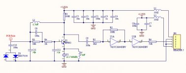
It should be "with unbuffered outputs" that's why U04 stands for... while you use this/those as an amplifier.
Hp
Ok, parts list updated.
Attachments
I have seen this claim but nothing that can support it. In terms of audibility it would take a lot of low frequency phase noise to create any audible modulations. The low frequency phase noise can be regarded as a form of wow on a turntable. Except that even the worst case LFPN is 50 dB lower that the best turntable ever for this parameter. The most sensitive region for jitter/phase noise would be in the higher frequencies, above 3 KHz. This is because the modulation products (F1 + F2 and F1 - F2) will be in the audible range and not close to any existing audio content. The linked article also mentions this.
Seems you know who claims that. I would trust him, since he has very long experience in this matter, he has built and tested thousands of oscillators.
The only thing I can say is that any decent oscillator reaches -150dBc at 3 kHz from the carrier, so they should perform the same regardless of the close to the carrier phase noise. But since jitter is related to phase noise, the subsonic region heavily influence jitter. The zero-crossing time will vary slightly from the ideal location since the signal is not strictly periodic due to noise.
If you compare the plots, jitter can vary more than an order of magnitude when the phase noise close to the carrier is very different.
I would be very suspicious of extraordinary claims about close in phase noise. It is by far the most difficult parameter to improve. The NIST article references performance for state of the art 5 MHz oscillators, ones that cost over $1500 ea and are considered "munitions" and restricted in sales. (I tried). If you scale those numbers (a valid thing to do) you get -108 at 1 Hz, -136 at 10 Hz, -156 at 100 Hz. Its possible to do some tricks and improve this a little. The best alternative for close in phase noise scaled to 20 MHz would be around -110 at 1 Hz, -125 at 10 Hz, and -131 at 100 Hz.
Remember that an AT-cut crystal can reach (theoretically) a Q up to 1M and more, and doubling the loaded-Q improves phase noise by 6dB (Leeson equation).
So, even an AT-cut crystal could reach high performance in phase noise.
Hi Andrea,
congratulation, very nice job, The Clapp oscillator seems to be very attractive.
What about other topologies? Have you ever played with them?
Did you try emitter coupled oscillators like in the attached schematic?
Not yet, next step are the Butler 2 emitters and Driscoll oscillators.
But if I will find the time ...
Hi
I'm interested, I have been looking into clocks recently, but not at the frequencies you are most likely to get.
I have some 24 and 25 Mhz clocks I want to upgrade. It seems unlikely that anyone else wants those frequencies, so I would either have to buy 5 or figure something else out. I don't really like either of those options.
Wondering how much the crystals are? (rough estimate kind of number)
Thanks
Randy
Hi
I'm interested, I have been looking into clocks recently, but not at the frequencies you are most likely to get.
I have some 24 and 25 Mhz clocks I want to upgrade. It seems unlikely that anyone else wants those frequencies, so I would either have to buy 5 or figure something else out. I don't really like either of those options.
Wondering how much the crystals are? (rough estimate kind of number)
Thanks
Randy
Hi Randy,
What frequency do you need precisely?
I think someone would be interested in 22.5792 MHz and 24.576 MHz, so please add your request and then we see if there will be enough interest.
Unfortunately the manufacturer does not produce less than 5 pcs.
Last time I bought the crystals I did pay around 35 CAD each (excluding shipping and VAT).
Andrea
OK, thanks for the info. I need exactly 24 and 25 MHz. They are for an audio PC. My DAC is a ES9018 using a crystek oscillator so I am less worried about upgrading that.
I'll figure out what I want to do and add my name to the list shortly.
Randy
- andrea_mori : 2 x 5.6448MHz + 2 x 11.2896MHz + 4 x PCB
- Eldam : 1 x 11.2896 Mhz + 4 x PCB
- esgigt : 1 x 11.2896 Mhz + 1 x PCB
- fralippo : 1 x 22.5792 MHz and 1 x 24.576 MHz + 2 x PCB
- mravinsky : 2 x 11.2896 Mhz + 1 x PCB
- TNT 1x22.5792MHz 1x24.5760MHz + 2 x PCB, soldered if possible
- Eldam : 1 x 11.2896 Mhz + 4 x PCB
- esgigt : 1 x 11.2896 Mhz + 1 x PCB
- fralippo : 1 x 22.5792 MHz and 1 x 24.576 MHz + 2 x PCB
- mravinsky : 2 x 11.2896 Mhz + 1 x PCB
- TNT 1x22.5792MHz 1x24.5760MHz + 2 x PCB, soldered if possible
Hi Randy,
What frequency do you need precisely?
I think someone would be interested in 22.5792 MHz and 24.576 MHz, so please add your request and then we see if there will be enough interest.
Unfortunately the manufacturer does not produce less than 5 pcs.
Last time I bought the crystals I did pay around 35 CAD each (excluding shipping and VAT).
Andrea
Andrea,
Have you thought about doing 22.5792 / 24.576 with a divide by 2
option. That will cover more bases and the phase noise won't be too
much worse.
The 22 / 24 MHz option is slightly less optimal WRT phase noise but you
do get 6dB improvement with the /2 option.
I'm pretty sure if you made a compact board that had both 22/24MHz, a
control IP to switch between them and a div by 2 option you would sell a
bunch of them.
cheers
Terry
Nice thought....Oh yes. A double frequency oscillator PCB could be very interesting nowadays for many people!

Andrea, would such a variant add much complexity to your current design?
I have thought about a divider/multiplier daughter board, here I could add the switch between 2 frequencies.
I would not modify the XO board to extend it to double frequency, since this not save space, and the cost of the board increases even for those who don't need this feature.
The daughter board could accommodate two XO board, the power supply for all the boards (+15V and +5V/3V3), a divider by 2/4/8, a multiplier by 2 and the switch between the 2 frequencies.
Probably the best way to implement the divider is using D flip-flop, while using a binary counter such as the 74LVC161 it will be more simple and flexible.
About the switch, a RF relays would be my best option, even if more expensive than a CMOS switch.
Please, let me know what do you think about and how many members were interested, so I evaluate this option.
Personally I'm not interested in divider/multipliers, also with the chance to get any freq. xtal produced it might not have much sense, but a daugher board that could accomodate two XO PCBs and custom designed PSUs for specific task and RF switching relay would be a great idea! It'd then easy to install divider/multipliers ICs - or not - depending on usage.
I'm not expert on this matter... but I guess that PSU quality is as much as important as oscillator one! As always in audio...
Also, should a different kind of oscillator perform better during tests, one could keep PSUs board and XOs and easily switch between different designs... if those PCBs will ever be produced.
Last edited:
Unfortunately going to 24.xx or 48.xx MHz crystals will require overtone operation with a more complex circuit. If there is a source for suitable crystals it is better to use one at the target frequency. The phase noise will be higher on a higher frequency crystal but less than a multiplier. Multipliers are simple but need a transformer and low noise Shottky diodes usually. A Minicircuits multiplier is cost effective: Mini-Circuits but not real cheap and then you still need to convert to LVTTL.
If you want low close in phase noise you can phase lock a higher frequency oscillator (49.152 MHz) to a lower noise low frequency oscillator (e.g. 6.144 MHz). You can get the low close in phase noise of the lower frequency with the higher actual frequency. Still more complexity but that's the price of performance.
The oscillator circuit for overtone crystals would need a suppressor (usually just an inductor) to ensure the crystal oscillates at the right frequency. The circuit would need to be tweaked to make sure the power in the crystal is not excessive. To make the circuit adjustable I think you could replace C8 with a varactor diode so you can pull the frequency a little.
- andrea_mori : 2 x 5.6448MHz + 2 x 11.2896MHz + 4 x PCB
- Eldam : 1 x 11.2896 Mhz + 4 x PCB
- esgigt : 1 x 11.2896 Mhz + 1 x PCB
- fralippo : 1 x 22.5792 MHz and 1 x 24.576 MHz + 2 x PCB
- mravinsky : 2 x 11.2896 Mhz + 1 x PCB
- TNT 1x22.5792MHz 1x24.5760MHz + 2 x PCB, soldered if possible
-1audio : 1x22.5792MHz 1x24.5760MHz + 2 x PCB
- Eldam : 1 x 11.2896 Mhz + 4 x PCB
- esgigt : 1 x 11.2896 Mhz + 1 x PCB
- fralippo : 1 x 22.5792 MHz and 1 x 24.576 MHz + 2 x PCB
- mravinsky : 2 x 11.2896 Mhz + 1 x PCB
- TNT 1x22.5792MHz 1x24.5760MHz + 2 x PCB, soldered if possible
-1audio : 1x22.5792MHz 1x24.5760MHz + 2 x PCB
- Status
- Not open for further replies.
- Home
- Source & Line
- Digital Line Level
- The Well Tempered Master Clock - Building a low phase noise/jitter crystal oscillator