I got my semifinished DriXO (5.6448) kit today. Looks good")
I also received the transformer kit, but I can't seem to find the information on which go where as they are not listed in the BOM. From pictures I deduce that the two taller ones (ADT16-6) are T2 and T3 and the lower one (ADT9-11) is T1.
Is this specified somewhere?
I also received the transformer kit, but I can't seem to find the information on which go where as they are not listed in the BOM. From pictures I deduce that the two taller ones (ADT16-6) are T2 and T3 and the lower one (ADT9-11) is T1.
Is this specified somewhere?
Yes wlowes, DRIXO board is a significantly better sound quality than the TWTMC-D DRISCOLL of the previous G.B,But to give a criticism founded the crystal must be burn.
Bottom end weight improvement is an immediate change i also found when i put in the these clocks just like the earlier clocks, as time goes on the details in the soundstage become more lifelike and holographic.
Definitely a substantial step up on the previous clocks

I'm very sorry for the delay, I will restart shipping as soon as I receive the 5/6 MHz crystals.
Unfortunately Laptech has informed me that they will receive the raw material in mid-May and then they have to work on the crystal to get the finished product.
So I think I will ship at the end of May.
Unfortunately Laptech has informed me that they will receive the raw material in mid-May and then they have to work on the crystal to get the finished product.
So I think I will ship at the end of May.
In the “how far can it go” category, I was exposed to some pretty far out things while doing sound for the BBC. The equipment was on a floating table so sensitive that the pressure of blood flowing through the veins in your finger tip lightly resting on the table would trigger an off the scale reading. This was in a room deep underground with a several foot thick vault door that would be closed on Friday so that things could settle before measurements were taken early on Sunday morning. Of course all the equipment was chilled with liquid nitrogen to remove most of the 1/f noise. All power was delivered via coaxial pipes that had a star ground that was centered at the physically lowest point in the room. Pure dc of course via what became superconducting paths at those temperatures. The atomic time reference was distributed via equidistant paths to all the critical nodes to ensure coherence and then returned to a comparator to check and possibly calculate out and deviations that might be detected. Of course this would be overkill for audio playback, unless it was also used to make the recording. ��. Everything matters I know but I am realizing the lack of my own imagination, not being able to imagine what the improvement to the listening experience will be from these new clocks. I can hardly wait to discover the as yet unknown. Thanks Andrea in advance for all your efforts in this endeavor.
Is/could there be any connection between 1/f noise and phase noise in relation to sound quality? generally that is, not just in clock circuits.
Increasing C2 capacitance on UltraBib regulator has the effect of decreasing 1/f noise. I noticed recently that increasing significantly from the stock value had quite a positive effect on overall sound of both analogue and digital circuits.
Increasing C2 capacitance on UltraBib regulator has the effect of decreasing 1/f noise. I noticed recently that increasing significantly from the stock value had quite a positive effect on overall sound of both analogue and digital circuits.
Last edited:
Initial impressions of WTMC 5mHz Drisco
Powered for 3 days the 5mHz Drixo is sounding great.
I believe the sound will continue to develop over the next weeks, but it is showing it’s stuff and it is good. My impressions mirror much that has been reported by others. I should mention that it replaces the fine 2019 45mHz Driscol.
My objective of a very natural relaxing sound is being realized. It is relaxed, rich but detailed. Sound has a very natural timbre. Voices and instruments are markedly more like the real thing than a machine attempting to recreate the sound. There is a shockingly good sound stage. Stable and life like. Devoid of fireworks… just real. Much sharper transient attack brings realism and engagement. Toe taps all the time and you want to listen to all the tracks. I find I want to listen to large well recorded orchestras from LessLoss, MA Recordings or Chesky. You hear the entire piece but easily follow any individual instrument.
While all of this is subjective, there are some obvious changes that can be measured. I was expecting an improvement in bass, and it is a little tighter and plays quite a bit lower. Looking at Spectroid on my android phone the changes are clear. My system used to be a bit peaked from 90-250Hz and definitely down from 1k to 10k. There was little ever above 12k. Now it is flat out to 15k before it rolls off. The waterfall diagram is uniformly bright across the spectrum from 40 – 15k and very clearly delineated. There is lots of info down to 34Hz. The entire spectrum sounds a little brighter and livelier. There is a substantial improvement in clarity and definition. Each instrument is separate from the next without being clinical.
Burn in is Required
The system really needed to burn in, and I am convinced it will continue to flush out over the coming weeks. On first power, it was clear that detail and definition would be better, but the sound was thin bright and unsatisfying. After 24hrs the low-level info was starting to fill in. But in this state, it was easy to see the stark increase in transient response. There were new details to hear in familiar tracks. But the sound was bad like a new capacitor. After 3 days it is well flushed out, but I expect to see more air develop.
Overall, it is a surprising improvement even over the first generation of Driscoll. Andrea is to be congratulated.
My setup needs a longer RG400 cable, and a couple weeks more burn in. I’m using a good 12” cable but not up to RG400 spec. It will be interesting to hear the change that a better cable that allows a bit more separation for TWTMC from the rest of the electronics.
The system
For reference, TWTMC is driving a fairly well resolved system. You can easily hear changes in components. TWTMC drives a FIFOPi / TDA1541a S2 / dual mono output Triode /streamer. The line stage is a Slagle autoformer. A pair of 110W OTL triode monos drive Lampizator P17 style open baffles. 10” Alnico full range and 18” bass drivers are pretty transparent.
Last edited:
Warning! This post could be hazardous to health of engineers
FWIW, I thought I’d share my implementation which focused on mechanical shielding and power. I use my full arsenal of audio fool Hokus Pokus, so proper engineers should stop reading now. Proceed with caution.
Based on the 2019 WTMC, I feel that these crystals are quite microphonic, and benefit from vibration dampening. I also heed Andrea’s advice to pay attention to RF/EMI shielding and to separate the clock in its own chassis well away from the DAC. I found PS to be important, but feel good is ok, and great may not be required. So rather than battery, I built a reasonable low noise linear supply which will be constantly powered.
Power Supply
It is supplied by 18v tap on a medical grade Plitron transformer. They tend to be very low noise. Panasonic FC filter caps are used (1500uF). After the first cap, there is a LM317 pre regulator taking it down to a pretty clean 22v. That’s followed by 3rd order CLC filters. Then a TPS7A4700 voltage regulator takes it to 16.51V. The reg has been modified with Black Gate caps. I believe this will provide clean power 7/24 for years to come.
Vibration / Isolation
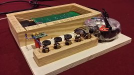
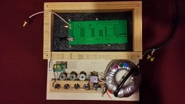
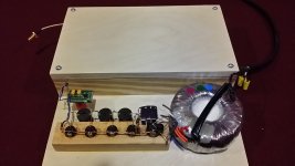
The power supply and the WTMC PCB are mounted on a Baltic Birch structure. The caps are potted with silicone in the wood. The WTMC floats inside a wooden box that is lined with foil. The entire wooden structure floats on silicone inside an aluminum chassis. All of this is to help with vibration dampening.
The PCB sits on packing foam in its wood box. On top of the PCB is a layer of dry sand. I find sand an excellent way to kill vibration. The Laptech crystal is sandwiched in it’s own block of foam which in turn is glued to the PCB. Per Andrea’s suggestion, it’s electrically connected with fine wires. The foam will provide temperature and vibration stability. The layer of sand compresses the PCB into the foam and isolates vibration. The wood has less ring than a metal chassis. The foil lining the box should provide some isolation from the PS. The metal chassis provides a reasonable isolation. The whole thing has mass, and layers of dampening.
But does it work? After 24 hours burn in in the wood box, I listened to some well-known tracks. Then I added the foil and sand and mounted the whole thing in the metal chassis. Then immediately listened to the same play list. There was a clear and substantial improvement in sound quality immediately apparent.
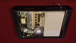
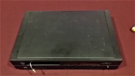
The pics below show the set up. I elected to build all of this from stuff on hand. So the chassis is a repurposed box from my old Arcam 1541a CDP. Seems kind of right that is still powers a TDA1541a based system.
FWIW, I thought I’d share my implementation which focused on mechanical shielding and power. I use my full arsenal of audio fool Hokus Pokus, so proper engineers should stop reading now. Proceed with caution.
Based on the 2019 WTMC, I feel that these crystals are quite microphonic, and benefit from vibration dampening. I also heed Andrea’s advice to pay attention to RF/EMI shielding and to separate the clock in its own chassis well away from the DAC. I found PS to be important, but feel good is ok, and great may not be required. So rather than battery, I built a reasonable low noise linear supply which will be constantly powered.
Power Supply
It is supplied by 18v tap on a medical grade Plitron transformer. They tend to be very low noise. Panasonic FC filter caps are used (1500uF). After the first cap, there is a LM317 pre regulator taking it down to a pretty clean 22v. That’s followed by 3rd order CLC filters. Then a TPS7A4700 voltage regulator takes it to 16.51V. The reg has been modified with Black Gate caps. I believe this will provide clean power 7/24 for years to come.
Vibration / Isolation
The power supply and the WTMC PCB are mounted on a Baltic Birch structure. The caps are potted with silicone in the wood. The WTMC floats inside a wooden box that is lined with foil. The entire wooden structure floats on silicone inside an aluminum chassis. All of this is to help with vibration dampening.
The PCB sits on packing foam in its wood box. On top of the PCB is a layer of dry sand. I find sand an excellent way to kill vibration. The Laptech crystal is sandwiched in it’s own block of foam which in turn is glued to the PCB. Per Andrea’s suggestion, it’s electrically connected with fine wires. The foam will provide temperature and vibration stability. The layer of sand compresses the PCB into the foam and isolates vibration. The wood has less ring than a metal chassis. The foil lining the box should provide some isolation from the PS. The metal chassis provides a reasonable isolation. The whole thing has mass, and layers of dampening.
But does it work? After 24 hours burn in in the wood box, I listened to some well-known tracks. Then I added the foil and sand and mounted the whole thing in the metal chassis. Then immediately listened to the same play list. There was a clear and substantial improvement in sound quality immediately apparent.
The pics below show the set up. I elected to build all of this from stuff on hand. So the chassis is a repurposed box from my old Arcam 1541a CDP. Seems kind of right that is still powers a TDA1541a based system.
Attachments
FWIW, I thought I’d share my implementation which focused on mechanical shielding and power. I use my full arsenal of audio fool Hokus Pokus, so proper engineers should stop reading now. Proceed with caution.
Based on the 2019 WTMC, I feel that these crystals are quite microphonic, and benefit from vibration dampening. I also heed Andrea’s advice to pay attention to RF/EMI shielding and to separate the clock in its own chassis well away from the DAC. I found PS to be important, but feel good is ok, and great may not be required. So rather than battery, I built a reasonable low noise linear supply which will be constantly powered.
Power Supply
It is supplied by 18v tap on a medical grade Plitron transformer. They tend to be very low noise. Panasonic FC filter caps are used (1500uF). After the first cap, there is a LM317 pre regulator taking it down to a pretty clean 22v. That’s followed by 3rd order CLC filters. Then a TPS7A4700 voltage regulator takes it to 16.51V. The reg has been modified with Black Gate caps. I believe this will provide clean power 7/24 for years to come.
Vibration / Isolation
The power supply and the WTMC PCB are mounted on a Baltic Birch structure. The caps are potted with silicone in the wood. The WTMC floats inside a wooden box that is lined with foil. The entire wooden structure floats on silicone inside an aluminum chassis. All of this is to help with vibration dampening.
The PCB sits on packing foam in its wood box. On top of the PCB is a layer of dry sand. I find sand an excellent way to kill vibration. The Laptech crystal is sandwiched in it’s own block of foam which in turn is glued to the PCB. Per Andrea’s suggestion, it’s electrically connected with fine wires. The foam will provide temperature and vibration stability. The layer of sand compresses the PCB into the foam and isolates vibration. The wood has less ring than a metal chassis. The foil lining the box should provide some isolation from the PS. The metal chassis provides a reasonable isolation. The whole thing has mass, and layers of dampening.
But does it work? After 24 hours burn in in the wood box, I listened to some well-known tracks. Then I added the foil and sand and mounted the whole thing in the metal chassis. Then immediately listened to the same play list. There was a clear and substantial improvement in sound quality immediately apparent.
The pics below show the set up. I elected to build all of this from stuff on hand. So the chassis is a repurposed box from my old Arcam 1541a CDP. Seems kind of right that is still powers a TDA1541a based system.
Nice report....
but, one thing concerns me a little, i see you have patched a coax to exit the wooden box... i guess you have soldered the end of the coax to the solderpad of the sma footprint on board.
I think in that position you have killed the constant impedance, and that hurts more than 10meter of cable after it.
I recommend, if i may, to keep the cables connected to the proper, impedance controlled connectors... you surely loose something, but signal integrity should be better ensured.
and also, if you can choose, prefer crimped termination instead of soldered one.
as always, my 2c
Hi gionag
Thanks,
I agree the soldered bulkhead cable is not ideal. I used what I had on hand.
When I order cables, I'll replace it with an SMA connector to bulkhead. I do not know to what extent it is an issue, but I'll change it if for no other reason to eliminate the concern. Looking at it, I find it hard to believe its much of an issue, but we'll find out when I change it.
Hello,
A medical grade transformer is one with a screen between the prim. and sec. side?
Rod Coleman ( makes heater supplies for DHT) always tells to use split bobbin transformer to get maximum separation between prim. and sec. side.
I am also not sure about the '' connection '' of the cable.
These clocks are sensitive to vibrations in the same way like a cartridge/tone arm/turntable combination?
The idea of Andrea to use thin wires is of course very clever because the circuit board is a big surface that will'' pick up '' vibrations, the coaxial cable and the power cable will also transfer vibrations to the board as well.
I think that like most vibration diminishing solutions foam, sorbothane, spring need a minimum load to actually work. If you mount the circuit in such a way that it will allow the clock to be attached to the board like a swing with two wires will it be influenced by airborne vibrations?
If so could you wrap it in some kind of foam ( just wrap the enclosure of the clock) ,some kind of felt made by natural fibers or piece of cork that can be found in all shapes and seizes.
If there is some space around the clock you can also make a little piece of cork to be glued to the board as an airtight '' enclosure '' which doesnt touch the clock at all.
Greetings, Eduard
- Status
- Not open for further replies.
- Home
- Source & Line
- Digital Line Level
- The Well Tempered Master Clock - Building a low phase noise/jitter crystal oscillator