SMS-200 clocking
@Anhton82
I also ordered these for SMS-200 (and 2...4 switches) clocking:
For 24Mhz:
1x 24.000 MHz SC-cut;
1x DRIXO-SF;
1x DRIXO XFMR 22-25 MHz;
1x STS-SX sine to square converter.
For 25 MHz:
1x 6.2500 MHz AT-cut;
1x PXO-AIO-SF;
1x AIO XFMR;
1x ST-SDFO-F dual (2x) sine to dual (2x) square output converter.
If you want to clock only SMS-200 choose STS-SX too for 25Mhz oscillator.
Can the PPG board accept a different frequency crystal, say 11.288427 MHz, maybe with some modifications?
No, the TWTMC-PPG was designed for 22/24 MHz only and the components value was calculated to be used with specifics HC-47/U standard (cheap) crystal.
For better crystals there are the DRIXO, the EXO, the PXO and the PXO-AIO oscillators.
@Anhton82
I also ordered these for SMS-200 (and 2...4 switches) clocking:
For 24Mhz:
1x 24.000 MHz SC-cut;
1x DRIXO-SF;
1x DRIXO XFMR 22-25 MHz;
1x STS-SX sine to square converter.
For 25 MHz:
1x 6.2500 MHz AT-cut;
1x PXO-AIO-SF;
1x AIO XFMR;
1x ST-SDFO-F dual (2x) sine to dual (2x) square output converter.
If you want to clock only SMS-200 choose STS-SX too for 25Mhz oscillator.
Thank you so much. I will follow this order. Because I need upgrade the Usb and Ethernet clock on SMS 200 and Drink Switch too.
I can endorse these statements. My 1541a based system took a big step forward with TWTMC from the last GB.What I can say is that several member in this thread have reported great improvement in sound when moving to a better oscillator, even using old DAC such as the TDA1541A.
That's the reason why tube amplifiers with 2% THD sound much better than solid state amplifiers with 0.0000...% THD.
And the reason is almost the same since usually amplifiers with such low distortion use heavily negative feedback. The NFB introduce phase shift and we perceive it as a timing error.
Typically the result is a non natural sound, loss of details and mostly ambience error..
Also resonate with your observations regarding triodes and feedback. My 6C33C based OTL amps have a switch to dial in more or less feedback. The lower setting is preferred by all with the subjective impression as you describe. Sense of ambience, image depth and air. Some will say I am assigning these impressions to increased distortion. I think not but either way everyone hearing it choses the low NFB setting.
I fully agree with your statement about the NFB.
I have built an audio system for a friend using the TDA1541A with the old TWTMC-D at 11.2896 MHz followed by a zero feedback 845 DTH power amp (a hevily tweaked chinese amp) and OB speakers.
The system sounds spectacular, one of the best system I have ever heard.
Female voices are so natural and correctly located in the stage that anyone has listened to the system believed the singer was in the room.
If I ever find the time I have all the components to build a zero feedback monobock solide state amplifier, where the active devices act as current pump without any voltage gain.
I am planning to experiment with WTMC in Network devices, 25 MHz, and the necessary parts are on order through a friendly helper. I will put the STS board inside the Network device, and provide a clean 3.3 VDC rail for it. The plan would be to use an SMA to SMA bulkhead jack, and a very short SMA-SMA cable from the rear panel to the STS board.
The question would be, what is best practice to connect the clock output and ground from the STS board, to the clock input (pad, SMD) on the device? Options:
1. I am handy enough that I could, likely mount a micro BNC to the board (u.fl), and then run a very short u.fl cable to the STS board output (it appears this board would require a direct soldering of the u.fl cable for output, right?). I can locate things such that this u.fl cable would be very short, perhaps 5 cm or less.
2. I could run a plain twisted pair of small gauge wires for clock output/ground and solder direct to the board pads, and to the STS board output, again very short, <5 cm.
At these lengths is either approach an advantage? Or is there a "better" way?
this...
This is off topic here, so I will make a quick response and not discuss it further. there have been many anecdotal reports of the Ethernet clock affecting sound quality in networked audio systems, the exact nature of how this happens is at present under investigation.
In any case, I intend to use the WTMC in this way to test the theory. Considering the low close in phase noise performance of this clock, if there is a difference, it should be obvious.
BTW, Quite a few folks in the group buy are purchasing 25 MHz variants for this purpose.
I can endorse these statements. My 1541a based system took a big step forward with TWTMC from the last GB.
Also resonate with your observations regarding triodes and feedback. My 6C33C based OTL amps have a switch to dial in more or less feedback. The lower setting is preferred by all with the subjective impression as you describe. Sense of ambience, image depth and air. Some will say I am assigning these impressions to increased distortion. I think not but either way everyone hearing it choses the low NFB setting.
I fully agree with your statement about the NFB.
I have built an audio system for a friend using the TDA1541A with the old TWTMC-D at 11.2896 MHz followed by a zero feedback 845 DTH power amp (a hevily tweaked chinese amp) and OB speakers.
The system sounds spectacular, one of the best system I have ever heard.
Female voices are so natural and correctly located in the stage that anyone has listened to the system believed the singer was in the room.
If I ever find the time I have all the components to build a zero feedback monobock solide state amplifier, where the active devices act as current pump without any voltage gain.
I agree as well..i'm in the camp of NOS DAC / DHT tube amps / open baffle speakers, and have no plans to switch in this life or the next
")
I am planning to experiment with WTMC in Network devices, 25 MHz, and the necessary parts are on order through a friendly helper. I will put the STS board inside the Network device, and provide a clean 3.3 VDC rail for it. The plan would be to use an SMA to SMA bulkhead jack, and a very short SMA-SMA cable from the rear panel to the STS board.
The question would be, what is best practice to connect the clock output and ground from the STS board, to the clock input (pad, SMD) on the device? Options:
1. I am handy enough that I could, likely mount a micro BNC to the board (u.fl), and then run a very short u.fl cable to the STS board output (it appears this board would require a direct soldering of the u.fl cable for output, right?). I can locate things such that this u.fl cable would be very short, perhaps 5 cm or less.
2. I could run a plain twisted pair of small gauge wires for clock output/ground and solder direct to the board pads, and to the STS board output, again very short, <5 cm.
At these lengths is either approach an advantage? Or is there a "better" way?
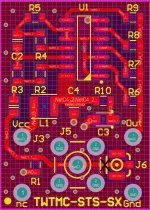
You can try to cut the trace between the input and J6, so you could use J6 as the output to connect the TWTMC-STS to your device using a 10 cm u.fl-u.fl cable.
Then you can connect the input to J5 using a SMA-SMA short cable from the pass-through SMA installed on the panel of the device.
Attachments
The reason is that we are very sensitive to timing errors while we are not so sensitive to THD.
That's the reason why tube amplifiers with 2% THD sound much better than solid state amplifiers with 0.0000...% THD.
And the reason is almost the same since usually amplifiers with such low distortion use heavily negative feedback. The NFB introduce phase shift and we perceive it as a timing error.
Typically the result is a non natural sound, loss of details and mostly ambience error.
For a minimum-phase or nearly minimum-phase system, the bandwidth determines the phase shift, so make an amplifier with a bandwidth extending from near zero to well in the megahertz range and you will have very little phase shift at audio frequencies, no matter whether or not you use feedback. Valve amplifiers with an output transformer and no feedback are probably the worst you can make in this regard, because the transformer limits the response on both sides and there is no feedback to partly correct that.
How do you hope to effect the SQ of a DAC by changing a clock in a switch?
//
Just with 'hope'...
Its probably an async dac too..
For a minimum-phase or nearly minimum-phase system, the bandwidth determines the phase shift, so make an amplifier with a bandwidth extending from near zero to well in the megahertz range and you will have very little phase shift at audio frequencies, no matter whether or not you use feedback. Valve amplifiers with an output transformer and no feedback are probably the worst you can make in this regard, because the transformer limits the response on both sides and there is no feedback to partly correct that.
On the other side a DHT is a linear device with very low odd harmonics (practically zero from 7th harmonic and above), while a solide state device is a non linear device that generates a lot of odd harmonics, not only 3rd harmonic but also 5th, 7th, 9th and so on.
Odd harmonics and mostly 7th and above are very deleterious for the perceived sound, they are the worst dissonances that we perceive as true annoyance.
Try with a piano.
The 7th chords are dissonant and therefore transitional towards a consonant chord, but if you overlap a 7th chord without the final transition the sound remains in a kind of suspension without completion so much so that it becomes annoying.
In the past I used to think of transformers as the devil but after several years of listening now I believe they are the best compromise.
There is also the OTL way if you don't like transformers, tubes like the 6336a are enough linear and provide enough current to drive a high sensitive speaker with a pair of them.
- Status
- Not open for further replies.
- Home
- Source & Line
- Digital Line Level
- The Well Tempered Master Clock - Building a low phase noise/jitter crystal oscillator