48k multiple PCM rates converted to DSD?
But reclocking is done after pcm to dsd conversation completed. So after conversation completed all of them is timers of 44.1Khz. Isnt it is wrong reclcok dsd with 48Khz?
Last edited:
But reclocking is done after pcm to dsd conversation completed. So after conversation completed all of them is timers of 44.1Khz. Isnt it is wrong reclcok dsd with 48Khz?
Let's say you have some 24/94 pcm files, HQplayer upsample them to 48k*128. Then you will need a XO in 49m to reclock it.
Sure you can run everything in 44.1k domain.
An interesting question has been raised.
Roon converter PCM-> DSD only in x44. HQPlayer also translates everything into domain 44 by default.
If you leave only 45Mgz for DSC2, you can shorten the MCLK path as much as possible. This will theoretically improve jitter.
maybe i dare too much... but i had an idea...
i had on hand 4 lifepo4 cells each @ 3.3v.
what happen if i bypass the regulators of the output stage on the dsc2 and then supply 6.6v (3.3+3.3 series) to each rail ?
i have red the datasheet for the NXP 74ahct595d and it says that the abs.max for voltage is 7 volt so i am "safe" here.
also noticed that the speed increase a little with voltage...
what do you think ?
It will work for at least an hour. A worst-case lifetime of an hour is usually all that is guaranteed under absolute-maximum-rated conditions.
Most likely it will work much longer than that, but the 74AHCT595 may slowly drift out of spec. The threshold voltages of the MOS transistors in the 74AHCT595 will increase and the betas decrease due to various effects that get much worse at increased voltages, such as hot carrier injection and negative-bias temperature instability. That will make the device slower, but probably not non-functional.
Most likely it will work much longer than that, but the 74AHCT595 may slowly drift out of spec. The threshold voltages of the MOS transistors in the 74AHCT595 will increase and the betas decrease due to various effects that get much worse at increased voltages, such as hot carrier injection and negative-bias temperature instability. That will make the device slower, but probably not non-functional.
An interesting question has been raised.
Roon converter PCM-> DSD only in x44. HQPlayer also translates everything into domain 44 by default.
If you leave only 45Mgz for DSC2, you can shorten the MCLK path as much as possible. This will theoretically improve jitter.
Down side is that it limits your choice of filters. So it is better to support both rate families.
At one point I was testing things with SiLabs oscillators that can have two frequencies you switch between using one of the four/six pins.
bisesik offers the manufacture of output transformers for any DAC - Output transformers for DACs
Ivan kindly provided me with a couple of transformers specially designed for DSC2 for testing.
I really like how they sound. I give them preference than standard chinese transformers.
Ivan kindly provided me with a couple of transformers specially designed for DSC2 for testing.
I really like how they sound. I give them preference than standard chinese transformers.
Attachments
Last edited:
bisesik offers the manufacture of output transformers for any DAC - Output transformers for DACs
Ivan kindly provided me with a couple of transformers specially designed for DSC2 for testing.
I really like how they sound. I give them preference than standard chinese transformers.
Highly interested, looks like they are pin compatible.
Also, did you measure the performance?
bisesik offers the manufacture of output transformers for any DAC - Output transformers for DACs
Ivan kindly provided me with a couple of transformers specially designed for DSC2 for testing.
I really like how they sound. I give them preference than standard chinese transformers.
Sorry pavel.... you are not allowed to behave like that

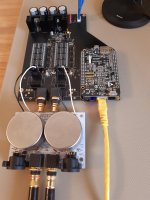
What on earth is the board you have there ?
details... i need details
bisesik offers the manufacture of output transformers for any DAC - Output transformers for DACs
Ivan kindly provided me with a couple of transformers specially designed for DSC2 for testing.
I really like how they sound. I give them preference than standard chinese transformers.
It is nice!
I took some time to make measurements of my DSC2 build (shown at https://www.diyaudio.com/forums/digital-line-level/254935-signalyst-dsc1-141.html#post5830294) before starting case construction. My results do not seem to be in-line with the measurements others are seeing. I'm wondering where I may have gone wrong and if there are any suggestions to get my THD measurements up to par with what other are seeing (https://www.diyaudio.com/forums/digital-line-level/254935-signalyst-dsc1-151.html#post5890188, etc).
While the measurements others have posted are around 0.007% THD, I am consistently seeing 0.013% in one channel, 0.017% on the other. I have attached my RTA spectrums.
Tests were run using a 1khz sine 384k/24bit wav file generated with SoX, -3db attenuation. This is upsampled to DSD512 or 256 in Roon (no meaningful differences in THD between the rates). Balanced output sends about 1.22V output to my Linear Audio Autoranger (which leaves attenuation to 0db) and then to my ESI Juli@'s balanced inputs.
Any thoughts on the cause of this? I have tried a few things to rule out some thoughts.
- Changed from a switch mode PSU with a cap-mx + regulator to a linear PSU + cap-mx + regulator. No changes in THD.
- Tried both SE and Balanced outputs, no change
- Tried HQPlayer instead of Roon for upsampling, no change
- Added 10k across the secondary of the output transformer (Lundahl LL1684), no change
Some suspicions I have:
- I ordered some 74AHCT595Ds from Taobao in an attempted to get old stock. It seems like they were based on NXP marking, but I wonder now if they are legit parts.
- It was stated by Vit123 that the Lundahls add significant distortion, but even for these transformers, is it expected to be this high?
- Any grounding issues? Right now its pretty isolated from anything, but I suspect this wouldn't be that big of an issue with balanced output. I also would assume any grounding issue wouldn't be spread across the harmonics as I'm seeing.
- Soldering or construction errors? Anywhere to start to check this? I read the previous posts about DC across the transformer primary. I measured and there is no substantial or constant DC voltage while playing music.
- Should I add additional snubbing or load to my output with the LL1684s?
- Perhaps my test setup is flawed.
Or... maybe these measurements are as expected with my build?
Any suggestions on where I can go next to try to lower the THD? Any other tests I should be running? Any other information that would be helpful?
Thanks all for your thoughts and expertise!
Greg
- Should I add additional snubbing or load to my output with the LL1684s?
Yes, in my case the waveform are very different when the tranformers are loaded.
What on earth is the board you have there ?
details... i need details
Do not worry.
According to the Open Hardware license, all DSC2 developments will be published in the public domain.
I got some free time. And also there were people who were ready to help bring the project to a commercial product for the HiEnd sector. The working name is DSD2extra. Only high-quality and expensive components will be used in the design. The board in the photo is just a model for testing new solutions on new microcircuits. The release will be in a different construct and in an expensive case. At the development stage, I can’t even imagine how much the finished copy will cost. Sales of this DAC do not interest me. The commercial side of things will be dealt with by other people.
Last edited:
Not yet measured.Highly interested, looks like they are pin compatible.
Also, did you measure the performance?
My measuring stand is now taken apart. It takes time to restore it.
Do not worry.
According to the Open Hardware license, all DSC2 developments will be published in the public domain.
I got some free time. And also there were people who were ready to help bring the project to a commercial product for the HiEnd sector. The working name is DSD2extra. Only high-quality and expensive components will be used in the design. The board in the photo is just a model for testing new solutions on new microcircuits. The release will be in a different construct and in an expensive case. At the development stage, I can’t even imagine how much the finished copy will cost. Sales of this DAC do not interest me. The commercial side of things will be dealt with by other people.
not worried at all... just anxious to upgrade my DSC
Good luck on that. If needed, i am here to help
An interesting question has been raised.
Roon converter PCM-> DSD only in x44. HQPlayer also translates everything into domain 44 by default.
If you leave only 45Mgz for DSC2, you can shorten the MCLK path as much as possible. This will theoretically improve jitter.
Great then can you share most simple way to do reclock with only one clock.
I saw https://puredsd.ru/BBBreclk.pdf but it a little bit complicated for me to lean it.
Or maybe you can add it on your latest design file
Do not worry.
According to the Open Hardware license, all DSC2 developments will be published in the public domain....
My wife starts to worry again ...
I'm so happy with my DSC2.5.2 that I need to build a backup equipment and that board seems to be perfect for the job!
if someone that is following is interested in one DSC2 fully operational, i am selling it over the swap meet section.
Is a good way to avoid some of the hassles involved in the building of such, for most, challenging device.
Is the second of the two's i have built. can't afford a second system at the moment
Is a good way to avoid some of the hassles involved in the building of such, for most, challenging device.
Is the second of the two's i have built. can't afford a second system at the moment
Last edited:
Hi mmerrill,
To be honest I don't remember whether I measured the distortion balanced or SE. My main objective was to observe when the logic started distorting and I remember it being pretty clearly happening around 1 mA.
Way back at post 563 there was a discussion about logic distortion starting at around 1mA.
I assume this 1mA relates to the nominal current through each resistor.
I see the current recommended resistors are 4k7-6k4 range, hence I assume set to be just under or on this point.
Has further analysis been done to qualify this, does anybody have any measurements they have saved?
Is the cause of the distortion yet understood?
Many thanks
bs
- Home
- Source & Line
- Digital Line Level
- Signalyst DSC1