SEN I/V changed to be pin compatible with AD844: don´t forget, +/-VS for SEN are floating...
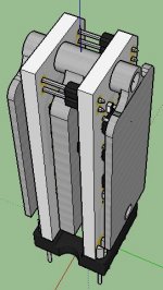
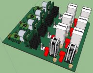
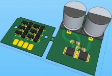
The I/V jfets run warm -- I use a 17mm chip heatsink to thermally couple the parallel BF862s. The larger holes in my board allow ties to secure the sinks.
... new task: cooling! @jborden: whats about the OPA temperature?
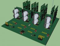
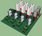
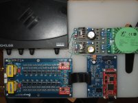
Here the mainboard (not routed but very good component placing).
Does a frontend list exists? Whats about reclocking, isolation?
- JLSOUNDS USBI2S
- AMANERO...
What else?
18V CCS = 2x PP9 (NiMH, LI+, LiPo, LifePO4...); NiMH with LM317 parallel charging?
Braining about +/-18V supply using 2x 6S LifePO4 Batteries with BMS...
JP
Attachments
... new task: cooling! @jborden: whats about the OPA temperature?
Here the mainboard (not routed but very good component placing).
Does a frontend list exists? Whats about reclocking, isolation?
- JLSOUNDS USBI2S
- AMANERO...
What else?
18V CCS = 2x PP9 (NiMH, LI+, LiPo, LifePO4...); NiMH with LM317 parallel charging?
Braining about +/-18V supply using 2x 6S LifePO4 Batteries with BMS...
JP
OPA: cooling not a big problem, it looks like you are thermally coupling the components which is, I think, the most important consideration.
Power: I'm using 2 9V batteries in series for testing purposes. Longer term plan is the "Dual bank floating supply" I posted in the power supply subforum.
Inputs: those are a good start -- I'd use @iancanada 's isolation/reclocking unit.
I am using @andrea_mori 's clock oscillators-- I'm working on a Zynq /FPGA based Ethernet input -> DSD output which runs off these clocks and has its own FIFO and then to a GMR isolation and D-flop reclocking, the isolation I'm employing has an inverting buffer so the DSD_EN which is + coming out of the FPGA gets inverted by the isolation stage -- the schematic posted expects an inverted DSD_EN.
The parts I'm using can handle DSD1024 i.e. 45/49 MHz clocks, and roughly double that to provide adequate margin or error i.e. DSD2048 might push the limits. I'm also designing 16 channels which would be possible with an efficient 1Gb Ethernet implementation.
<JAB.R>
Hello @carlsor,
I´ve questions:
- are isolators between Amanero and your board (#396) an improvement?
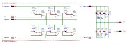
- what is the purpose for C7, C8 (values?) and R36 (470R)?
- is XOR 86 a better solution then a BCLK clocked D Flip-flop 74 for DSD-R/L inverting?
- if no DSD stream (glue logic around MUTE and DSD-ON) then +2.5V (VCC/2 of 595) before I/V (using TI analog switches)?
JP
I´ve questions:
- are isolators between Amanero and your board (#396) an improvement?
- what is the purpose for C7, C8 (values?) and R36 (470R)?
- is XOR 86 a better solution then a BCLK clocked D Flip-flop 74 for DSD-R/L inverting?
- if no DSD stream (glue logic around MUTE and DSD-ON) then +2.5V (VCC/2 of 595) before I/V (using TI analog switches)?
JP
Hello JAB.R
How do you solve the mute problem?
JP
That is best solved in the USB->DSD or Ethernet->DSD driver.
The original glue logic from the DSC1 could be included.
At the driver level there are optimizations available including providing a clock family signal as well as soft start/dithering etc that can solve clicks at rate/song transitions.
I'm not sure where Amanero etc are in this. I've set mine aside as I'm working on the direct Ethernet->DSD route.
Attachments
Last edited:
Well done!
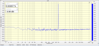
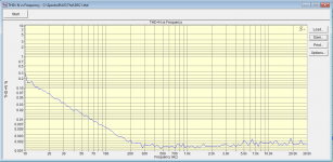
The noise looks fairly high compared to most modern DACs but distortion
looks very good.
- Is this at max OP
- Were you using AK4137 to convert to DSD for DSC1?
cheers
T
I think that the noise level below 120db satisfies the parameters of high-quality sound reproduction.The noise looks fairly high compared to most modern DACs but distortion
looks very good.
What is "OP"? I make measurements always at -10db. This is similar to the average weighted level of most music records.zenelectro said:- Is this at max OP
Yes, I use AK4137 to convert PCM to DSD. The output format was set by DSD128. DSD256 slightly increases THD from 0.00086% to 0.0018%.zenelectro said:- Were you using AK4137 to convert to DSD for DSC1?
I think that the noise level below 120db satisfies the parameters of high-quality sound reproduction.
If the 'grass' or noise floor on FFT is around -120dB then that does not mean
the RMS noise floor is -120dB. 20k BW RMS noise floor will be around -100dB
depending on the no of points of FFT sweep. A DAC that has true -120dB
noise floor will show the FFT 'grass' at around the -150dB level with a 20k
BW sweep.
Many people get fooled by this and many manufacturers misquote their
performance specs due to this misunderstanding. That's just noise theory.
What is "OP"? I make measurements always at -10db. This is similar to the average weighted level of most music records.
Yes, OP = Output. The reason I asked is because at 0dB (full scale) is where
most DAC's struggle WRT distortion and it can rise significantly.
Yes, I use AK4137 to convert PCM to DSD. The output format was set by DSD128. DSD256 slightly increases THD from 0.00086% to 0.0018%.
Interesting WRT DSD 256. I would expect the opposite but it might be
related to logic switching finite speed.
WRT resistor matching, on this design it should not make any significant
difference, that's just the way the moving average filter works.
Overall though a pretty good result. I think to get better measured performance than this on a discrete design would take some real design
effort.
- Which clocks are you using and..... most importantly...
how does it sound?
T
If the 'grass' or noise floor on FFT is around -120dB then that does not mean
the RMS noise floor is -120dB. 20k BW RMS noise floor will be around -100dB
depending on the no of points of FFT sweep.
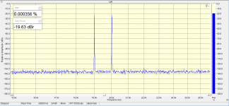
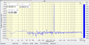
0.000857% THD+N gives -101.34 dB as total noise level for the measurement bandwidth, including distortion.
That's measured with -0db level without AK4137. The DSD128 dsf file is converted from WAV by the saracon program.Yes, OP = Output. The reason I asked is because at 0dB (full scale) is where
most DAC's struggle WRT distortion and it can rise significantly.
I also think that the problem is speed.zenelectro said:Interesting WRT DSD 256. I would expect the opposite but it might be
related to logic switching finite speed.
Lowering the output resistors of the matrix improves the matching with the 10K transformer.zenelectro said:WRT resistor matching, on this design it should not make any significant
difference, that's just the way the moving average filter works.
Amanero with Crystek.zenelectro said:- Which clocks are you using and..... most importantly...
how does it sound?
Both versions - balanced and not balanced - have a strongly pronounced analog sound. I would call it "vinyl sound". I really like him.
The non-balanced version is a little in the lead in subjective comparison. But in a non-balanced version, the correlation noise at low volume is annoying.
Attachments
That's measured with -0db level without AK4137. The DSD128 dsf file is converted from WAV by the saracon program.
I also think that the problem is speed.
Lowering the output resistors of the matrix improves the matching with the 10K transformer.
Amanero with Crystek.
Both versions - balanced and not balanced - have a strongly pronounced analog sound. I would call it "vinyl sound". I really like him.
The non-balanced version is a little in the lead in subjective comparison. But in a non-balanced version, the correlation noise at low volume is annoying.
WRT 0dB FS - that is an excellent measured result.
Are you feeding the transformer from after opamp I-V or are you just feeding
resistor matrix straight into transformer?
I think this design needs to feed virtual ground for best performance.
Edit - PS I think also the results can be skewed by ADC in test set (EMU?)
Nice results!
Transformers are connected directly to the resistors.Are you feeding the transformer from after opamp I-V or are you just feeding
resistor matrix straight into transformer?
Attachments
Last edited:
- Home
- Source & Line
- Digital Line Level
- Signalyst DSC1