Bricasti DSD DAC
I cannot get them to tell me if they do anything to the incoming DSD, except they do say it always remains single bit. The DAC has an AD SHARC processor onboard, which does handle the oversampling/filtering using custom filters, for PCM input.
The discrete DSD DAC section consists of a high speed switch (IC), followed by a discrete filter circuit made up of precision resistors and film capacitors. There are four of these circuits, I presume two for each of the two (balanced) circuit paths. This looks to be similar to what Playback Designs does. I have had some experimental DSD DACs here using similar approaches, but they all had some noise issues. I like to test the noise floor by playing a file which has a 1 kHZ tone at -90 dB, one can then turn this way up, and still hear what the noise floor sounds like (my Purifi amp has so little noise the audible floor is basically that of the DAC). The Bricasti noise floor with the DSD DAC section is clear and smooth.
BTW, this same test with my (Pavel) DSC-2 is interesting, one thing it proved to me is that this DAC is performing better with DSD 256 than 512 in my set up, as the noise floor with DSD 512 starts to get a bit weird, uneven, with some static sounds sticking out. But the floor is smooth and clean with DSD 256 input. Of course this may also be related to the oversampling engine, my tests were with Roon oversampling, not with HQPlayer, yet... One can hear the results of different modulators, etc, with this test as well. Next thing to try would be to make up some non-related, low level multi tones, with some higher level tones thrown in, to then listen to the floor for modulation effects which are signal correlated.
Bricasti are an interesting Pro Audio company that don't necessarily take the
usual approach to design. The AD1955 DAC chips are an example of this.
Their M7 digital reverb unit is absolutely superb.
They are ex-Lexicon folk, Lexicon being basically the forefather of digital audio reverb / special effects.
Does the M3's use something like a discrete resistor pulse arrray DAC for
DSD? They might well also be 'pre conditioning' the DSD data stream before
it is sent to the DAC arrays.
TCD
I cannot get them to tell me if they do anything to the incoming DSD, except they do say it always remains single bit. The DAC has an AD SHARC processor onboard, which does handle the oversampling/filtering using custom filters, for PCM input.
The discrete DSD DAC section consists of a high speed switch (IC), followed by a discrete filter circuit made up of precision resistors and film capacitors. There are four of these circuits, I presume two for each of the two (balanced) circuit paths. This looks to be similar to what Playback Designs does. I have had some experimental DSD DACs here using similar approaches, but they all had some noise issues. I like to test the noise floor by playing a file which has a 1 kHZ tone at -90 dB, one can then turn this way up, and still hear what the noise floor sounds like (my Purifi amp has so little noise the audible floor is basically that of the DAC). The Bricasti noise floor with the DSD DAC section is clear and smooth.
BTW, this same test with my (Pavel) DSC-2 is interesting, one thing it proved to me is that this DAC is performing better with DSD 256 than 512 in my set up, as the noise floor with DSD 512 starts to get a bit weird, uneven, with some static sounds sticking out. But the floor is smooth and clean with DSD 256 input. Of course this may also be related to the oversampling engine, my tests were with Roon oversampling, not with HQPlayer, yet... One can hear the results of different modulators, etc, with this test as well. Next thing to try would be to make up some non-related, low level multi tones, with some higher level tones thrown in, to then listen to the floor for modulation effects which are signal correlated.
i have also noticed the very same dsd-512 behaviour on my past dsc-2.
then i switched to mcfifo+dsc 2.6.2 and the noise went away.
with the St!cks, same thing. DSD512 all day and never had some "strange" noise issues.
i must confess that i always suspected that trace layout on the dsc2 was a little bit clumsy, nor impedance matched in any way (neither on the 2.6.2, but there was much larger clearences) and i think the increase in frequency lends more opportunity to trigger noise along the path in case traces was not carefully layed down.
... the stick's attaches to the McFifo / McDualXO combo from IanCanada.
on the DualXo i am using the adpater to mount the NDK SDA 45.xxx and 49.xxx
nothing fancy here
well, funcy enough the McFifo ... I've got one too, I did not recall by your picture, but I have it. So I might end up replicating your project if you do not mind.
thanks mate
The output trafos from bisesik right ?. I got a pair a while ago, they are fantastic. My trafos are 1:5, we found out that it was the best output ratio for the DSC.
surely i don't mind at all...
on the contrary, I encourage you to do it, they sound amazing (to my ears... of course)
BTW the otp xfrmr are biseik nonetheless, in ratio 1:5 (old version) as yours.
I just need time and willing to finalize all the docs (schematic, component placement, gerbers, bom ecc.. ecc...)
and also, i don't want to speak too soon, but maybe there's something going on with ian and the mcfifo for the dsc applications...
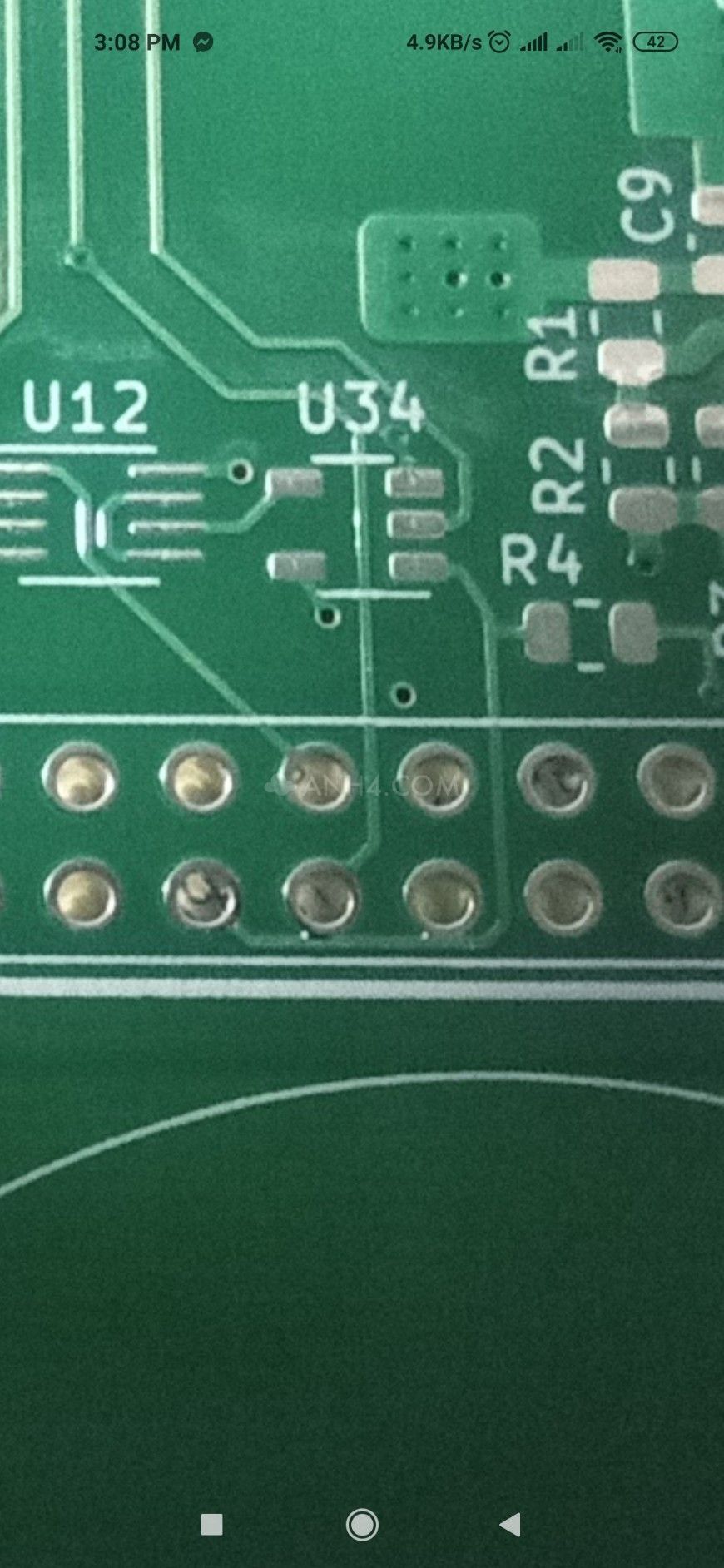
My PCB ") ). Thank you ppy.
). Thank you ppy.
). Thank you ppy.An externally hosted image should be here but it was not working when we last tested it.
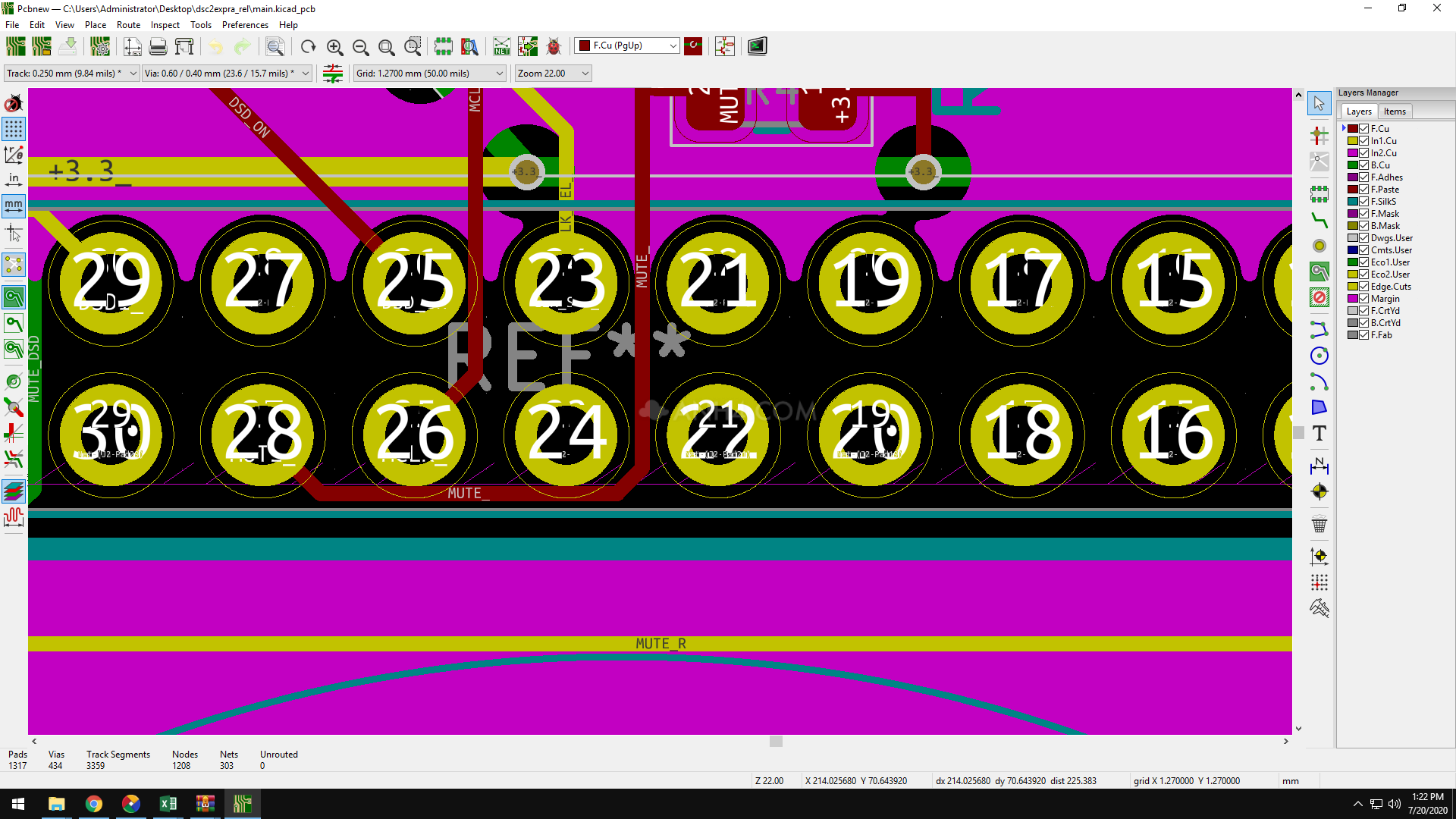
I think here it is an layout error.
Cool. Where can I get my hands on those gerber files or do you maybe by any chance have some leftover PCB's?
For Ivan's transformers with a large coefficient, the question arose again with the quality of the mute signal.
Slightly changed the mute signal in the firmware for the BeagleBone.
New mute signal on P9/28. This pin needs to be connected to +3.3V via 4.7K.
The old signal is retained at P9/27.
The new signal analyzes the state of Alsa and Roon, HQP players. Works better than Botic driver signal. Ideally, you need to mute the OE registers. But current PCB do not allow this.
sd_botic7.img (2).gz — Yandex.Disk
In the new firmware, after Linux is fully loaded, all LEDs are turned off. The system boots in about 2 seconds.
Last edited:
I encourage you to do it, they sound amazing (to my ears... of course)
BTW the otp xfrmr are biseik nonetheless, in ratio 1:5 (old version) as yours.
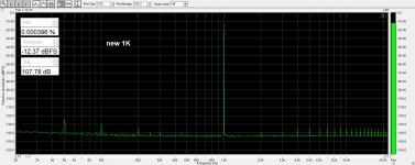
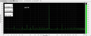
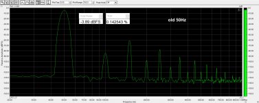
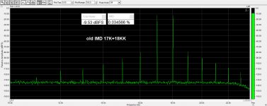
Newer versions of transformers sound very good. And their measurements are also very good. This is practically the limit for my E-MU 0204.
Attachments


Cool. Where can I get my hands on those gerber files or do you maybe by any chance have some leftover PCB's?
Signalyst DSC1

... Ideally, you need to mute the OE registers. But current PCB do not allow this ...
while developing the Sticks i have thought about that implementation... i was not sure how effective would be, so i have reverted to the classical analog switch across the output.
At the moment i am using the mute signal coming from the McFifo itself, that bit aligned, open a little before the music starts, and a little before it stops...
i have tried driving the mute from the beaglebone, but was not ideal with a fifo in the middle ( as you can imagine... )
if i redo the boards, i will leave this option open to try it out....
I already remembered after posing my question, that Pavel posted the Gerbers back in May. Thanks anyway and if anyone got some PCB's made from those Gerbers and wants to sell one PCB to me or someone wants to do so and is thinking about doing a groupbuy, please send me a pm
It is necessary to simultaneously operate the OE and the analog switch.while developing the Sticks i have thought about that implementation... i was not sure how effective would be, so i have reverted to the classical analog switch across the output.
There are two reasons:
- When there is no DSD signal, the registers of one shoulder at the output are "1" and the registers of the opposite shoulder are "0". This is a serious load for an analog switch.
- The resistance of the primary winding of Ivan's transformers is ~3 ohms. And the resistance of the public key is ~0.5. Therefore, an analog switch is not efficient.
Last edited:
Is there a possible advantage to varying the bit length of the converter for differing input data rates? For example, instead of the standard 16 bits, use 20 bits for DSD512, and 12 bits for DSD64?
Also, and excuse me if this has been previously addressed, is there any advantage to using a reclocker such as the Twisted Pear Cronus/Rhea ?
Am planning to construct a DSC-2 with the tube output board from the RAKK DAC, if I can find parts or plans for one ...
Also, and excuse me if this has been previously addressed, is there any advantage to using a reclocker such as the Twisted Pear Cronus/Rhea ?
Am planning to construct a DSC-2 with the tube output board from the RAKK DAC, if I can find parts or plans for one ...
It is necessary to simultaneously operate the OE and the analog switch.
There are two reasons:
- When there is no DSD signal, the registers of one shoulder at the output are "1" and the registers of the opposite shoulder are "0". This is a serious load for an analog switch.
- The resistance of the primary winding of Ivan's transformers is ~3 ohms. And the resistance of the public key is ~0.5. Therefore, an analog switch is not efficient.
... mhhh yes, but we always have the 5k resistor in between, so the "load" would be rather small.
the "high" shoulder impose 5v, the lower a 0, 5k between the two halves (so 10k).
5v / 10k = 500uA.
but maybe you are referring to the inductive "kick" from the transformer primary...
First problem:
Very often there is a moment when DSD data is missing but MCLK is working. Then 32 register outputs are switched to "1" and the opposite ones to "0".
5K/32=156Ω
5V/312Ω=16mA
Second problem:
Inductive "kick" is not in our case. But too little difference between the resistance of the analog switch (0.5Ω) and the resistance of the primary winding (3Ω) weakens the click by only ~16db
while developing the Sticks i have thought about that implementation... i was not sure how effective would be, so i have reverted to the classical analog switch across the output.
At the moment i am using the mute signal coming from the McFifo itself, that bit aligned, open a little before the music starts, and a little before it stops...
i have tried driving the mute from the beaglebone, but was not ideal with a fifo in the middle ( as you can imagine... )
if i redo the boards, i will leave this option open to try it out....
That is the issue with almost every single interface. I did proper logic (for amanero) BUT signal coming from interface is wrong. Going active just before music starts or with changing sample rate or else and opposite before stop...
I thnik that You can use some power on reset IC to adjust this delays? I am going to try it for sure.
One question please:
What part is this resistor stack IC You are using?
Last edited:
- Home
- Source & Line
- Digital Line Level
- Signalyst DSC1