2 Versions
Here are two versions of the board/routing. Opinions as to which tradeoffs are best? In both cases the Signalyst DSC1 design with the shift register FIR filter is used. Boards are 4 layers with solid GND and VCC planes. A potato semi D flip flop is used to generate the DSD' signal for the (-) side of the balanced design. A potato semi 1:10 clock buffer is used. This has probably the lowest output device to output device skew (<80 picosecs) in a 1:10 clock buffer. power supply bypass cap networks are used. The susumu rg 15k 0.05% 10ppm 0603 resistors are used in the ladder. VCC = 3.3V. Clock trace lengths are matched to 0.2mm
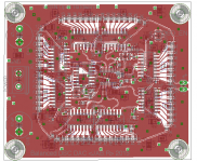
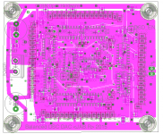
#1: all chips (shift registers) and clock traces on the top layer, so no vias on clock or data lines. Clock traces are ~17.5mm
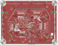
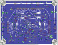
#2: the (+) and (-) shift registers are mirrored on the top and bottom layers of the board. 1/2 of the clock traces traverse a via and so a via is placed on all clock traces to match capacitance. An extra 1.6mm is placed on the top layer clock traces to match via traversal. Clock traces are thus ~24.2mm
So which should be better?
Here are two versions of the board/routing. Opinions as to which tradeoffs are best? In both cases the Signalyst DSC1 design with the shift register FIR filter is used. Boards are 4 layers with solid GND and VCC planes. A potato semi D flip flop is used to generate the DSD' signal for the (-) side of the balanced design. A potato semi 1:10 clock buffer is used. This has probably the lowest output device to output device skew (<80 picosecs) in a 1:10 clock buffer. power supply bypass cap networks are used. The susumu rg 15k 0.05% 10ppm 0603 resistors are used in the ladder. VCC = 3.3V. Clock trace lengths are matched to 0.2mm
#1: all chips (shift registers) and clock traces on the top layer, so no vias on clock or data lines. Clock traces are ~17.5mm


#2: the (+) and (-) shift registers are mirrored on the top and bottom layers of the board. 1/2 of the clock traces traverse a via and so a via is placed on all clock traces to match capacitance. An extra 1.6mm is placed on the top layer clock traces to match via traversal. Clock traces are thus ~24.2mm


So which should be better?
Can easily look at that though I'm using iancanada's Dual XO II to reclock after FIFO
Sent from my iPhone using Tapatalk
It's an interesting project, but how do you get I2S output from a PC?
It seems that from a Linux NAA its not possible (yet):
http://www.diyaudio.com/forums/twisted-pear/258254-support-botic-linux-driver-135.html#post4508776
Here are two versions of the board/routing. Opinions as to which tradeoffs are best? In both cases the Signalyst DSC1 design with the shift register FIR filter is used. Boards are 4 layers with solid GND and VCC planes. A potato semi D flip flop is used to generate the DSD' signal for the (-) side of the balanced design. A potato semi 1:10 clock buffer is used. This has probably the lowest output device to output device skew (<80 picosecs) in a 1:10 clock buffer. power supply bypass cap networks are used. The susumu rg 15k 0.05% 10ppm 0603 resistors are used in the ladder. VCC = 3.3V. Clock trace lengths are matched to 0.2mm
#1: all chips (shift registers) and clock traces on the top layer, so no vias on clock or data lines. Clock traces are ~17.5mm
View attachment 517187
View attachment 517188
#2: the (+) and (-) shift registers are mirrored on the top and bottom layers of the board. 1/2 of the clock traces traverse a via and so a via is placed on all clock traces to match capacitance. An extra 1.6mm is placed on the top layer clock traces to match via traversal. Clock traces are thus ~24.2mm
View attachment 517185
View attachment 517186
So which should be better?
I read somewhere that via's capacity can be problematic with clock signal.
It's an interesting project, but how do you get I2S output from a PC?
It seems that from a Linux NAA its not possible (yet):
http://www.diyaudio.com/forums/twisted-pear/258254-support-botic-linux-driver-135.html#post4508776
Ultimately might be good to get direct I2S, alternatively run HQPlayer's networkaudiod on an FPGA/ARM SOC that has an SFP ethernet input and direct I2S output but today the JLSounds or Amanero boards USBtoI2S boards also output DSD over I2S including the DSD_EN line. I am planning to feed the DSDR,DSDL and BCLK lines into the iancanada chain of FIFO ISOLATE AND RECLOCK.
I read somewhere that via's capacity can be problematic with clock signal.
That's the issue.
The idea of mirroring the logic chips is a sound one. One could even use the same power trace, or put both chips behind the same inductor/capacitor chain and so the switching spikes would then theoretically cancel, but this all depends on the chips switching at precisely the same time and that's where a delay caused by the vias could entirely negate the benefit of mirroring the chips.
#1: all chips (shift registers) and clock traces on the top layer, so no vias on clock or data lines. Clock traces are ~17.5mm
This is technically better for the digital side...
#2: the (+) and (-) shift registers are mirrored on the top and bottom layers of the board. 1/2 of the clock traces traverse a via and so a via is placed on all clock traces to match capacitance. An extra 1.6mm is placed on the top layer clock traces to match via traversal. Clock traces are thus ~24.2mm
Intuitively I like this better as it has potential to utilize common mode rejection for the analog side if it works well enough at the digital side. I think this has some good potential and it would be great if this can be just tried out and see how it performs!
Using here somebody the dac with linux or with naa + linux? I experienced a loud click noise with osx when resolution was changed. The solution was to use windows (as mentioned here before), but how about linux?
Click & pop is because of DoP, and Amanero not utilizing enough look-ahead buffer to control mute before change in data happens. This is a common problem with DoP because DSD information is bound to the data.
Using ASIO drivers on Windows makes this easy, as DAC can know upfront whether data is going to be PCM or DSD well in advance before any data is being transferred.
Recommendation is to have mute engaged for first 100 ms of DSD data, and then engaged 100 ms before the data ends. This makes the turn-over happen silently.
The Problem, that i would like to use a Beaglebone Linux NAA, but native DSD driver doesnt exist for Amanero yet. The solution will be jlsounds i2s audio card that has driver and galvanic isolation too.
This (#1) is technically better for the digital side...
...
Intuitively I like this (#2) better as it has potential to utilize common mode rejection for the analog side if it works well enough at the digital side. I think this has some good potential and it would be great if this can be just tried out and see how it performs!
I've got both sets of boards on order from OSHPark. I don't have a Ghz scope nor fancy test equipment to properly determine if I have the mirrored design right. I am happy to share the project if anyone else wants to test this out (this project is CERN Open Hardware of course
Balanced DSC boards
Boards arrived:
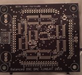
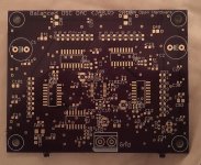
The parts are inexpensive -- majority of cost are the Susumo RG series 15k 0.05% 10ppm resistors.
Both boards are SMD double sided, the first mostly bypass caps and the chokes that filter each chip. The mirrored version obviously has chips on both sides.
Its going to take some time for me to build, get all the components together to test, needing to build the I-V (sen variant bf862/j111 cascode) and SK filters (jfet buffer based) as well as Salas reflektor-d supplies for digital side, NiCad battery suppies for I-V etc.
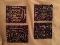
For reference, the schematics used:
Clock path optimized:
View attachment DSC1b.JAB.R.clockopt.pdf
Mirrored:
View attachment DSC1b.JAB.R.mirror.pdf
Boards arrived:


The parts are inexpensive -- majority of cost are the Susumo RG series 15k 0.05% 10ppm resistors.
Both boards are SMD double sided, the first mostly bypass caps and the chokes that filter each chip. The mirrored version obviously has chips on both sides.
Its going to take some time for me to build, get all the components together to test, needing to build the I-V (sen variant bf862/j111 cascode) and SK filters (jfet buffer based) as well as Salas reflektor-d supplies for digital side, NiCad battery suppies for I-V etc.

For reference, the schematics used:
Clock path optimized:
View attachment DSC1b.JAB.R.clockopt.pdf
Mirrored:
View attachment DSC1b.JAB.R.mirror.pdf
I'm posting this as I've received a few requests. Ideally I'd be able to test the boards before publishing. That said, any help testing these out is appreciated. Likewise input on improvements. This version expects u.fl inputs.
Balanced DSC DAC digital board-clock optimized OSMPark project:https://oshpark.com/shared_projects/JoYj5uwD
OSHPark Mirrored project: https://oshpark.com/shared_projects/BrLbszwQ
There are some unspecified value termination resistors and cap that you can decide. I am using Johanson bypass caps but obviously any that you'd prefer can be used.
Attachments
Thank you for sharing this!
I'm posting this as I've received a few requests. Ideally I'd be able to test the boards before publishing. That said, any help testing these out is appreciated. Likewise input on improvements. This version expects u.fl inputs.
Balanced DSC DAC digital board-clock optimized OSMPark project:https://oshpark.com/shared_projects/JoYj5uwD
OSHPark Mirrored project: https://oshpark.com/shared_projects/BrLbszwQ
There are some unspecified value termination resistors and cap that you can decide. I am using Johanson bypass caps but obviously any that you'd prefer can be used.
So tempting, but I'm torn about which one to build.
I think Jussi's analysis is probably right.
I have no way to model the extent to which mirroring the shift register chips will ameliorate common mode noise. The mirroring isn't perfect for a couple of reasons:
1) clock come in on one side -- there might be a systemic difference in clock signal skew between the (+) and (-) sides and this might do more harm than good -- OTOH I might have gotten the timing close enough
2) the board is 4 layered: (+) : GND : VCC : (-), so one side of the mirror is closer to GND and the other VCC ... would this create a systemic difference?
I am assuming that most of the noise is digital switching noise, this is the design attempts to ameliorate this:
1) Solid GND and VCC planes.
2) EFI Bead on each chip
3) multiple bypass caps on either side of the bead
4) high Q bypass cap network: 100nF x 2, 1nF, 100pF, 10pF (or whatever values you'd like)
Personally I have reels and tubes of these parts, and the only way I know is to build both and compare ... I hope I can hear a difference (which I probably won't be able to
It is interesting that some folks discuss the so-called 'femtosecond' clocks because I can't find a clock distribution circuit that can approach that. The potato semi clock buffer has a pin to pin skew of <80 psec which is as good as I could reasonably find for a 10 way chip (<50psec for 4 way clock buffer)
FYI on what I'm using: EFI beads are Murata 220ohm 0805. Caps: high q/low esr, C0G "RF" etc, Johanson etc. Termination resistors: 33 ohm, 50 ohm. Feel free to jumper the termination cap.
So any ways if you don't have a lot of experience in double sided SMD boards -- here's good practice, particularly the mirrored board -- just let us know which sounds better
Last edited:
Hats off to the new closed form filter outperformed others by a big margin.
closed form 11.2m
http://i.imgur.com/EKGV1TH.png
closed form 5.6m
http://i.imgur.com/DcHsOUz.png
poly-sinc-mp2 22.5m
http://i.imgur.com/9TYssbX.png
closed form 11.2m
http://i.imgur.com/EKGV1TH.png
closed form 5.6m
http://i.imgur.com/DcHsOUz.png
poly-sinc-mp2 22.5m
http://i.imgur.com/9TYssbX.png
- Home
- Source & Line
- Digital Line Level
- Signalyst DSC1