I'm shopping around for four stereo DACs of the inexpensive variety, e.g. FiiO D03k, etc. After poking around Ebay for awhile I came across a couple of these built DAC boards for $20-$25. These have a single SPDIF coax input and analog stereo output. Description indicates CS8416 (receiver) and CS4398 DAC. Looking at the pic of the board, there is no transformer on the SPDIF input. For $20 I am not expecting the world, but was wondering if anyone had taken the plunge with this board or could give some comments on the expected performance.
I need coax SPDIF to analog conversion 24bits at 48kHz minimum. This will be put in a case with other stuff, so pcb is fine. Suggestions for alternates welcome.
Link: CS8416 CS4398 24bit 192K Coaxial DAC Decoder Board Assembled | eBay


I need coax SPDIF to analog conversion 24bits at 48kHz minimum. This will be put in a case with other stuff, so pcb is fine. Suggestions for alternates welcome.
Link: CS8416 CS4398 24bit 192K Coaxial DAC Decoder Board Assembled | eBay
Maybe good enough for your kitchen and if you don't spend time in it !
from my seat :
smd but not compact ?
I can not see the crystal XO
no polymer cap or not visible ?
CS8416 in software mode (not external clock) : i believe thi schip has far more jitter than let say: Wolfson 88004/5.
it seems there is an oap buffer, but wich one ?
DC blocker output capacitor seems very poor and not bipolarised.
the one of hifimediy is 3 time expensive but maybe you have more in SQ for dolar to dolar : Hifimediy CS4398 DAC "direct out", TCXO oscillator
- TCXO oscillator
- DSP for spidf input (but mayber noiser than CS8416... I don't know)
- sanyo polymer cap
- direct output (no buffer) with Mundorf cap at DC blocker
- Panasonic FM for DC supply
In fact maybe this one is more economic at the end
Just 2 cents, but IMHO your link is for me a perfect exemple of crap kit, you have even the shipping cost with it, for 25 dollars
How about this SPDIF--> R/L analog DAC kit?
I have seen it sold in many places, including here at NewEgg:
Newegg.com - CS4398 CM102 CS8416IC DAC Kit 192K 24bit SPI I2S Amplifier Board
This is an LJM designed board I believe. I would need to build it, but it is doable for me.
Thoughts?
I have seen it sold in many places, including here at NewEgg:
Newegg.com - CS4398 CM102 CS8416IC DAC Kit 192K 24bit SPI I2S Amplifier Board
This is an LJM designed board I believe. I would need to build it, but it is doable for me.
Thoughts?
On the picture @newegg I see AK4393 DAC chip, only SPDIF input. I had one in picture - with AK, it performs... well it has some sound coming out However my attempts to attach Tenor board to it to use with USB were unsuccesful - a lot of dropouts and errors. SPDIF from CD player works fine.
However my attempts to attach Tenor board to it to use with USB were unsuccesful - a lot of dropouts and errors. SPDIF from CD player works fine.
Last edited:
Bad Chineese DAC are good to learn and test personal tweaks...(I did on a AD1865 DAC Kit) and for 25 bucks it's like to go to cinema... you will have a good time to test better value caps, change the buffer OAP and output caps... But of course special needs or joy of tweaking I'm not sure this is a great deal because if your are on DIYA this is because you are demanding with listening.. You will tell us if you are pleased wit it unmodified. Maybe it can be a surprise for the bucks ?
Do you think the DAC chip is fed by the internal X0 from the CS8016 spidf receiver ? ... I can not see any crystal on the captched pictures ?
I saw there are good 4 layers PCB kit with ES9018 tested at Hifiduino if you have more specific needs. This one is maid by the official chineese distributor of ES. Very good construction and PCB quality... but it stays a PCB maid for diyers (not SOTA layout).
Last edited:
First inspection of DAC board
Well, I purchased the DAC board and have just received it, about 10 days later. Not bad for free shipping.
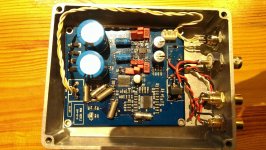
I can now look at the board close up. It's labeled "X6M VER 1.0" and "2013-07-27". No hand soldering, it's all professionally done. Power comes in as 12-0-12V AC and is then rectified and filtered with discrete diodes and two 2200uF caps. There is a pair of 7812 and 7912 regs, as well as a separate 5V and two separate 3.3V regs (not sure yet of the part, but might be 317 type). The input to the 8416 from the coax is via an R to ground and an SMD cap. I have seen this scheme used before and its fine but not transformer isolated. The output of the CS4398 is buffered through a TI N5532.
I plan/hope to test this out soon and will post some results.
Well, I purchased the DAC board and have just received it, about 10 days later. Not bad for free shipping.
I can now look at the board close up. It's labeled "X6M VER 1.0" and "2013-07-27". No hand soldering, it's all professionally done. Power comes in as 12-0-12V AC and is then rectified and filtered with discrete diodes and two 2200uF caps. There is a pair of 7812 and 7912 regs, as well as a separate 5V and two separate 3.3V regs (not sure yet of the part, but might be 317 type). The input to the 8416 from the coax is via an R to ground and an SMD cap. I have seen this scheme used before and its fine but not transformer isolated. The output of the CS4398 is buffered through a TI N5532.
I plan/hope to test this out soon and will post some results.
Ah, now we are getting to the thick of the matter! Can our little el cheapo board measure well at least, and sound good? Note: see attachments for measurements.
I connected a dual secondary 12VAC transformer to the board, and used an M-Audio ProFire 610 to run some tests. I connected the SPDIF output on the 610 using a short section of Belden 1505A cable that I had lying around (75 ohm characteristic impedance) and then one channel of the analog output section back to the #3 line input of the M-Audio.
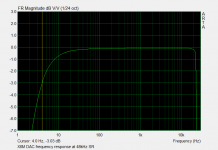
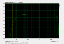
I ran frequency response and distortion tests at 48kHz and 96kHz. I could not get output from the DAC at 192kHz although it is listed as 24/192.
As you can see from the attached files, the frequency responses at 48kHz and 96kHz look fine. No problems.
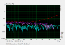
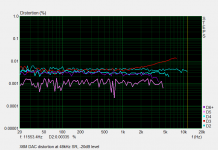
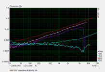
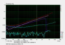
The problems appear when you look at the distortion. I first measured the distortion at 48kHz and 96kHz at -3dB level. THD starts low, around 0.001% at 20Hz, but increases with frequency and has reached a whopping 0.1% by 10kHz, consisting of odd order products. The even order distortion products are significantly lower (See plots).
Next I re-measured the distortion with the level 20dB lower for both sampling rates. The results were quite different - this time only 3rd order distortion was rising with frequency, only reaching about 0.02% by 10kHz. All the other distortion products essentially remained in the noise floor.
Seeing that this is a bargain basement DAC, I am wondering if the two larger grey caps labeled 10uF 63V that are on the analog outputs are junk and what we are seeing is primarily distortion from these caps. I might try and replace them with something else, although the only 10uF film caps that I have are physically too large for the board.
If the question is "can a $20 DAC perform well" I think the answer is a resounding "no" for this one. The rising distortion performance is really unacceptable for this kind of equipment (a DAC). I would not use this DAC for full range listening.
On the other hand, if your requirements are for a very low cost DAC that will only be used at "lower" frequencies this board may still be passable. For instance if you only need this for a subwoofer, below 100Hz, the distortion is very low (circa 0.001%) and the frequency response is -3dB at 4Hz. Excellent. You could even use it below 1kHz if you can live with distortion levels rising up to about 0.01% at full scale output, less (<0.003%) for levels around -20 or less. This would be fine.
I have not yet "listened" to the DAC. I will do that thru some headphones to check for any sonic issues, clicks, pops, etc and post them if I find any.
-Charlie
I connected a dual secondary 12VAC transformer to the board, and used an M-Audio ProFire 610 to run some tests. I connected the SPDIF output on the 610 using a short section of Belden 1505A cable that I had lying around (75 ohm characteristic impedance) and then one channel of the analog output section back to the #3 line input of the M-Audio.
I ran frequency response and distortion tests at 48kHz and 96kHz. I could not get output from the DAC at 192kHz although it is listed as 24/192.
As you can see from the attached files, the frequency responses at 48kHz and 96kHz look fine. No problems.
The problems appear when you look at the distortion. I first measured the distortion at 48kHz and 96kHz at -3dB level. THD starts low, around 0.001% at 20Hz, but increases with frequency and has reached a whopping 0.1% by 10kHz, consisting of odd order products. The even order distortion products are significantly lower (See plots).
Next I re-measured the distortion with the level 20dB lower for both sampling rates. The results were quite different - this time only 3rd order distortion was rising with frequency, only reaching about 0.02% by 10kHz. All the other distortion products essentially remained in the noise floor.
Seeing that this is a bargain basement DAC, I am wondering if the two larger grey caps labeled 10uF 63V that are on the analog outputs are junk and what we are seeing is primarily distortion from these caps. I might try and replace them with something else, although the only 10uF film caps that I have are physically too large for the board.
If the question is "can a $20 DAC perform well" I think the answer is a resounding "no" for this one. The rising distortion performance is really unacceptable for this kind of equipment (a DAC). I would not use this DAC for full range listening.
On the other hand, if your requirements are for a very low cost DAC that will only be used at "lower" frequencies this board may still be passable. For instance if you only need this for a subwoofer, below 100Hz, the distortion is very low (circa 0.001%) and the frequency response is -3dB at 4Hz. Excellent. You could even use it below 1kHz if you can live with distortion levels rising up to about 0.01% at full scale output, less (<0.003%) for levels around -20 or less. This would be fine.
I have not yet "listened" to the DAC. I will do that thru some headphones to check for any sonic issues, clicks, pops, etc and post them if I find any.
-Charlie
Attachments
Update: I did some listening today, as well as some A/B comparisons with an M-Audio ProFire 610 that I use for measurements and so on. I also was able to get the Ebay DAC to operate at 192kHz - the earlier problem had to do with how I set up the measurement software and not the DAC itself.
I listened to a variety of music for several hours through headphones. It was surprising to discover that I really could not discern any of the distortion that I had measured, or any differences between the DACs. I actually was "listening for" the distortion at first, but then I realized that I couldn't really hear it. This might be due to the average level being lower where the distortion performance is much better and only brief transients reach the higher digital levels that resulted in the high odd order distortion.
This DAC is so inexpensive, you might want to try and pick up one and see for yourself if you also find its performance acceptable. Not a top contender by any means, but I did not find any major faults either.
Hello Charly,
If i had read your thread before, i would't have bought the PCB.
I have got an idea why this dac performes so bad.
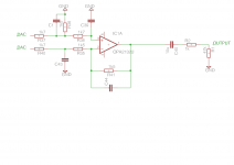
In the attachment is the suggested "minimalistic" filter.
As you can see, there is a second cap preventing the DAC driving a permanent DC current.
Adding this cap would be a easy tweak (all in all i'd like to modificate SMD more than DIL)
To you have the possibility to check, if the PCB has the chematics of the datasheet?
I can count 4 ceramic caps per channel and 6 resistors. The part's count does fit with it.
My second Idea is, that those ceramic caps are so bad, that they couse the "outstanding" disturtion.
My PCB will arrive in a few weeks and my goal is to tweak this little pcb to the datasheet performance (even then, jitter performance won't be very good, but for such a cheap dac?)
If i had read your thread before, i would't have bought the PCB.
I have got an idea why this dac performes so bad.
In the attachment is the suggested "minimalistic" filter.
As you can see, there is a second cap preventing the DAC driving a permanent DC current.
Adding this cap would be a easy tweak (all in all i'd like to modificate SMD more than DIL)
To you have the possibility to check, if the PCB has the chematics of the datasheet?
I can count 4 ceramic caps per channel and 6 resistors. The part's count does fit with it.
My second Idea is, that those ceramic caps are so bad, that they couse the "outstanding" disturtion.
My PCB will arrive in a few weeks and my goal is to tweak this little pcb to the datasheet performance (even then, jitter performance won't be very good, but for such a cheap dac?)
Attachments
Last edited:
Sorry I can't trace the PCB. It seems to be more than 2 layer.
In a similar thread on another forum some on-board SMD caps were identified as the main culprit of the rising distortion at higher input levels. I bought another board with the same ICs but using film caps as the output filter and it has a relatively flat distortion profile. I think that the builder just wanted to make a small and cheap DAC.
As I pointed out, if you used this only for low frequencies there is no problem and performance is fine in that application.
My DAC arrived very fast.
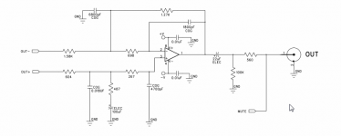
I traced the Analogue Filter chematics for the Right Channel.
At least that, there is no CAP in the positive DAC output does stress the DAC with a permanent 3k Load.
A little bit tweaking, and it's the original one.
I traced the Analogue Filter chematics for the Right Channel.
At least that, there is no CAP in the positive DAC output does stress the DAC with a permanent 3k Load.
A little bit tweaking, and it's the original one.
Attachments
Last edited:
My DAC arrived very fast.
I traced the Analogue Filter chematics for the Right Channel.
At least that, there is no CAP in the positive DAC output does stress the DAC with a permanent 3k Load.
A little bit tweaking, and it's the original one.
What do you add/change? Sorry I could not follow it. Can you give more details please?
Sorry for my very bad written last post!
If you compare the original schematics from CS and the ebay dac schematics you will notice that both are using the same topology.
There are slight differences:
The CS one does have a second elec cap to avoid DC current. I will add this cap.
The values for parts seems strange in the CS chematics, but they are making sense for low noise.
The values of the resistors are "hard to find" (farnell does have those values but i'd like to go to a local store!). So i give a try with other values:
R40-> 1,58k ----> 1,6k
R35-> 698 ----> 680R
R41 -> 1,27k ----> 1k2
R37 -> 604R ----> 619R
R38 -> 267R ----> 270R
R36 -> 487R ----> 470R
R2 --> 560R ---->100R
This gives a CMRR which is better than the 1% resistor tolerance.
What's harder to find are good npo caps with the suggestet values in SMD. So i will go for MKS02 RM2,5 Caps.
I choose:
C44 -> 1n8 ---> 2n2
C43 -> 6n8 ---> 6n8
C39 -> 4n7 ---> 4n7
C1 (this number seems to be wrong) -> 18n ---> 22n
All Parts are for one channel, the other one is mirror inverted on the board.
This will give you not a perfect filter response, but we are talking about a cheep dac, so i don't like to spend too much on presision parts.
Parts are around 5€ in Germany
I haven't finished the modification untill now, but i will do the mod on the weekend.
Last edited:
I'm interested in seeing the results of your experiment.
My problem with the DAC was only the performance as signal level approached digital 0dB (maximum output). Within about 10dB of this, the distortion performance had a rising character that exceeded 0.1% distortion by 20kHz dominated by odd order products. But at lower levels (e.g. -20dB) the DAC had more of a flat distortion profile with THD levels well below 0.01% except for a slight rise of 3rd order above 10kHz. You can see my measurements in post#9 in this thread.
I got some feedback that this distortion behavior is characteristic of non-NP0 type ceramic caps. So it's good that you are replacing the SMD caps with better types (MKS) in addition to adding the elcap.
Can you do some distortion testing after adding the MKS caps and before adding the elcap? It would be interesting to see the relative influence from these two modifications on any improvements that occur...
I don't know if i had the time to make those tests.
The Problem is that i don't have a good ADC at home. In university lab i have acsess to simmilar gear, but in the moment everyone is in stress there.
If you do some modifications on the resistors, the elcap is necessary because the DAC can only drive 1k and will be saturated by the DC current.
I think changing the caps is the best (and most easy) modification. Ill try to measure the original ones for you.
Hello out there!
It takes a long time for me to get a running Setup.
In the moment i use the ADC of a Terratec TS22 Soundcard (i think it was a AKM Chipset).
Because i had a OPA 1642 in stock, i changed the NE 5532.
Aditionally i added a few Tantals on the board and bypassed the output Caps with foil ones.
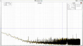
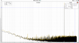
The first screenshot was measured with 2vpp
The second screenshot was shoot with a load of 100Ohm (with a output resistor of 270Ohm). You get around 10db less output voltage but the THD did not rise at all.
I think the THD is limited by the ADC and think i am on specs now.
Can anyone help me out with the right grounding?
In the moment the Case is grounded with the chinch connectors to anal. ground. The Spdif input went trought a transformer and isn't earthed at all. The Powersupply is not conneced to the case.
It takes a long time for me to get a running Setup.
In the moment i use the ADC of a Terratec TS22 Soundcard (i think it was a AKM Chipset).
Because i had a OPA 1642 in stock, i changed the NE 5532.
Aditionally i added a few Tantals on the board and bypassed the output Caps with foil ones.
The first screenshot was measured with 2vpp
The second screenshot was shoot with a load of 100Ohm (with a output resistor of 270Ohm). You get around 10db less output voltage but the THD did not rise at all.
I think the THD is limited by the ADC and think i am on specs now.
Can anyone help me out with the right grounding?
In the moment the Case is grounded with the chinch connectors to anal. ground. The Spdif input went trought a transformer and isn't earthed at all. The Powersupply is not conneced to the case.
Attachments
Last edited:
I did another modification on the DAC:
I power it from a single wall mart supply and noticed that the ripple on the positive voltage supply was around 500mV with the typical peaks (If you supply it with a dual supply the ripple decrease, but even 250mV are a lot!).
I decided to use a CRC Network with aditional 2200uf and a 10Ohm Resistor. That takes the powersupply ripple down to 50mV with much less peaks in it.
This help's to remove the 50Hz Humm on the output.
Hello out there!
It takes a long time for me to get a running Setup.
In the moment i use the ADC of a Terratec TS22 Soundcard (i think it was a AKM Chipset).
Because i had a OPA 1642 in stock, i changed the NE 5532.
Aditionally i added a few Tantals on the board and bypassed the output Caps with foil ones.
The first screenshot was measured with 2vpp
The second screenshot was shoot with a load of 100Ohm (with a output resistor of 270Ohm). You get around 10db less output voltage but the THD did not rise at all.
I think the THD is limited by the ADC and think i am on specs now.
Can anyone help me out with the right grounding?
In the moment the Case is grounded with the chinch connectors to anal. ground. The Spdif input went trought a transformer and isn't earthed at all. The Powersupply is not conneced to the case.
Good job! This is definitely an improvement on the performance.
Usually you would ground the case to earth ground, but with a wall wart power supply that isn't available. Using the PS ground like you are doing is second best. I'm pretty sure that the spdif input should not be earthed.
- Status
- This old topic is closed. If you want to reopen this topic, contact a moderator using the "Report Post" button.
- Home
- Source & Line
- Digital Line Level
- ebay SPDIF dac "CS8416 + CS4398" only $25 - worth a try?