Mmm, it is a KISS DAC so no other LED than a dim glowing green "power on" LED. Why people like bright shining blue LEDs lightening the whole living room is beyond me. A lock LED would have been nice but I guess you will hear that it locks on the incoming SPDIF stream, sorry I could not resist ")
No earth/PE on the PCBs, you must connect casing to earth (if you use a metal case) but if I tell my personal choice then AndrewT will be here to punish me immediately.
I think audio GND and earth/PE should not be connected. Here I said it, feels like an introduction on an AA meeting. PE pollutes audio electronics but please don't listen to my unsafe/dangerous ramblings and follow legal electrical guidelines of the country you live in. We also forgot to mention you can not dry the DAC after cleaning in a microwave oven (before anyone starts about that).
BTW why no U6 (3.3 V MIC ) ? It will not work without U6... Oh and the DAC PCB is B+ but the PSU PCB needs some resoldering.
Last edited:
This area is a little confusing. It appears there is an option here or a pad is missing. Any info?
I don't think Mr. T knows we are here yet, so we might be able to stay under the radar - Though I really do appreciate his consistent demands for "Safety First".
I have U6, just haven't placed it yet. Will do when I solder U1.
I don't think Mr. T knows we are here yet, so we might be able to stay under the radar
- Though I really do appreciate his consistent demands for "Safety First".I have U6, just haven't placed it yet. Will do when I solder U1.
Attachments
Last edited:
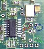
From BOM, for C35 they recommend MAL212856478E3 a Vishay SAL-RPM. I believe Newark has them. For C32, 667-EEU-FC1H4R7 a Panasonic Alumimunm, 4.7 uF, 50V. Thats what I am going with. You could also use 581-TAJB475K016 SMD tantalum which is specified on the BOM for C5, C7, C15, C16, C17, C19, C20, C26, C27. Not sure any option would make a difference in sound as C32/C35 are in parallel with C34 and C31 on the NEG pin of the DAC chip. I do not see how they could make a difference, but I am sure some of the smart folks around here might have a different opinion.
Got my boards today - going to need my 2.5x flip up magnifying glasses I use for fly fishing to solder these!. Tying tiny #28 midges this fall will come in handy on this project.
Waiting for a Mouser order to get started. Also purchased this SMD Soldering Practice Kit to get my feet wet:
SMD Soldering Practice Kit - Top Sellers
Last edited:
That kit is great. Even though I've done SMD soldering before, a little practice with that would have been a great help. Thanks for the link.
I have C31 placed on the bottom of the PCB and assumed it was a bypass. Looks like I need to rethink that.
Please take and post lots of pictures as you build. Can never have too many.
I have C31 placed on the bottom of the PCB and assumed it was a bypass. Looks like I need to rethink that.
Please take and post lots of pictures as you build. Can never have too many.
Small advice after soldering 3 kits: do not solder L3,4,5,6 before first powering up. In this way you can check all four regs and voltages without damaging Receiver and dac chips.
Bob, i'm really interested about your impressions especially considering you are using the akm4396 dac also.
Bob, i'm really interested about your impressions especially considering you are using the akm4396 dac also.
Last edited:
Yes Bob, all 3 kits are running now. I had one clock damaged from excesive heat i suppose so take care. Solder wick is the best help for smd soldering for me.
The test ponts are the pads of every L3,4,5,6 wich are connected to the Micrel regs.
Tomorrow i will post a picture if needed.
The test ponts are the pads of every L3,4,5,6 wich are connected to the Micrel regs.
Tomorrow i will post a picture if needed.
Last edited:
All 3 sounding good Atupi ?
Bob, you need C34 + C35 or C34 + C32 and in both cases you can use a SMD cap at the underside of the PCB. Always use C34 ! Try to have a total sum of capacitance larger than 2 µF but not larger than 22 µF.
We did this because MAL128 caps are different in footprint and some of you wanted pads for different caps...Vneg pin is a sensitive one. You will have better results when using larger capacitance than the data sheet value of 1 µF.
Last edited:
Yes Jean-Paul, all 3 sounding great (two are for some friends). On one i'm using a 12mhz osc until i can source a 50mhz one. Those small smd oscillators seems to be temp sensitive.
I have bought looong time ago also a buffer from Joachim Gerhard wich is waiting to be connected
Thanks again Jean Paul for this really great sounding Dac.
Adrian
I have bought looong time ago also a buffer from Joachim Gerhard wich is waiting to be connected
Thanks again Jean Paul for this really great sounding Dac.
Adrian
Congrats Adrian !! Gotta have that sound quality report,
Yes. a graphic of any sort would be appreciated.
JP, this may be asking a lot, but I think we all could use a description of those spots that allow options - all in a single post. Can you create a summation from both your builds and the significant reports from others like atupi? There will most likely be more adjustments in the future, but a little hand holding for those of us without great circuit chops would be appreciated at this start-up phase.
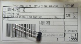
B1 in psu BOM
hey,
i started on the psu tonight. the mouser part (which i purchased) listed for B1, 512-DF01S, doesn't seem right and also doesn't match the mfgr part W01G-E4/51.
512-DF01S is actually an SDIP-4 smd part. even with bending the leads for "through hole" it won't fit the footprint.
the correct mouser part seems to be 625-W01G-E4.
-matt
edit: i see that this was discussed already in the main GB thread
hey,
i started on the psu tonight. the mouser part (which i purchased
) listed for B1, 512-DF01S, doesn't seem right and also doesn't match the mfgr part W01G-E4/51.512-DF01S is actually an SDIP-4 smd part. even with bending the leads for "through hole" it won't fit the footprint.
the correct mouser part seems to be 625-W01G-E4.
-matt
edit: i see that this was discussed already in the main GB thread
Last edited:
Congrats Adrian !! Gotta have that sound quality report,
Yes. a graphic of any sort would be appreciated.
JP, this may be asking a lot, but I think we all could use a description of those spots that allow options - all in a single post. Can you create a summation from both your builds and the significant reports from others like atupi? There will most likely be more adjustments in the future, but a little hand holding for those of us without great circuit chops would be appreciated at this start-up phase.
Start-up phase
Wow that is something for a project running for more than a year in the third revision Regarding options/other parts: regarding caps, I use whatever I have at hand and since I stock many caps I use what I have and what tests to perform good. Some of those are either hard to get or out of production like BG. Like the MAL cap which I have in stock, I guess I wouldn't have chosen those otherwise. Expensive, hard to find etc. just like its predecessor the Black Gate cap. I like the Silmic II too. Maybe that is one of the available caps that always perform well regardless of the device. You can't go wrong with Panasonic FC as well. Point is that I can not recommend what is not available. If you would like my opinion I will tell you to use BG NX HiQ (old news).
Also XO can be interchanged, Fox Xpresso (in the BOM) is good, Euroquartz XO91 are OK too. To be honest I think all has been discussed before and I want to finish this project as a new one is on the horizon. Maybe one of you has the time to bundle all info ? Most things that were valid for V2.6 are valid for V3. The BOM should be enough really.
V3 is a cheap DAC, better performing than competitors but still a cheap device. We can for instance debate for months which resistors to choose but IMO that is not the scope of the project. I understand that every individual building just one DAC will want to know what is best but if you are building example number 25 things get different. We ourselves use the coils, resistors, SMD beads and SMD ceramic caps that are in the BOM but we use different electrolytic/tantalum caps and different XO's now and then. Also PPS SMD caps were used before but I think they are too easily damaged from soldering so I stopped using those.
Last edited:
Thanks autpi. I'm past that point but it's a nice safety step for others just starting. I hope I don't get any stinky green smoke when I power up tomorrow.
JP, I wasn't clear enough in my earlier post. I should have said "new builders" not "start-up". Better?
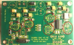
Also, I wasn't asking for info on the many possibilities of parts in general. I was only referring to those places that have markings and/or clear definitions on the BOM. Should have defined "options" not "alternatives". The spots circled on the photo and the PS transformer 120v/230V + F1 selection were my targets. Not sure if those on the DAC should be consistent in package type, or if they can/should be mixed in the user tweaking process.
JP, I wasn't clear enough in my earlier post. I should have said "new builders" not "start-up". Better?
Also, I wasn't asking for info on the many possibilities of parts in general. I was only referring to those places that have markings and/or clear definitions on the BOM. Should have defined "options" not "alternatives". The spots circled on the photo and the PS transformer 120v/230V + F1 selection were my targets. Not sure if those on the DAC should be consistent in package type, or if they can/should be mixed in the user tweaking process.
Attachments
I posted some comments about my experience building a prototype version 3 earlier this year. Take a look here:
http://www.diyaudio.com/forums/group-buys/237612-subbu-dac-v3-es9023-wm8804-spdif-power-supply-pcb-group-buy-60.html#post3698767
---Gary
http://www.diyaudio.com/forums/group-buys/237612-subbu-dac-v3-es9023-wm8804-spdif-power-supply-pcb-group-buy-60.html#post3698767
---Gary
- Home
- Source & Line
- Digital Line Level
- Build thread - building the Subbu DAC V3 SE