I have seen different approaches to this;
See this PCM1794A audio DAC and PupDAC at http://www.diyforums.org/PupDAC/schematic/pupDACschematic-3.gif , both are using only resistors instead of the inital opamp stages in the reference design http://www.ti.com/lit/ds/symlink/pcm1794.pdf , page 20.
What do you think, which is better?
Seems the simpler designs still have some sort of filtering with the capacitor directly on the current outputs.
I took the hint from the Bel Canto DAC2 and use opa1632 as I/V converters after a pcm1798. Sounds good to me.
Two things to watch for :
- the opa1632 doesn't like capacitive loading so it's best to avoid caps in // with the I/V resistors. Put the filter on the next stage.
- the vcom pin of the opa1632 set the output voltage and not the input voltage. So you can't tie it to ground. If you did so, you would have a voltage at the DAC's output equal to your I/V resistor's value multiplied by the pcm1794's current offset (which isn't good). So you need to feed the vcom with a suitable voltage reference to bring the voltage at the pcm1794's output down to 0.*
Btw, if you go down the "simple resistors" road, you shouldn't use more than 22r.
* Which is why I wouldn't use an IVYIII from Twisted Pear on PCM179* DAC.
Last edited:
driving Cload doesn't have much to do with feedback caps if you're not using noise gain input C to gnd too, the negative input "virtual gnd" really isn't real gnd
in fact the OPA6132 datasheet has an example with 1 nF feedback C
not knowing the DAC Iout Z can't really say if it would work but the reasoning should be kept straight
in fact the OPA6132 datasheet has an example with 1 nF feedback C
not knowing the DAC Iout Z can't really say if it would work but the reasoning should be kept straight
Btw, if you go down the "simple resistors" road, you shouldn't use more than 22r.
According to the datasheet, PCM1794 can feed 7.8 mA p-p, would it not bottom out with that 22R if max voltage is 5 V? It seems PupDAC has 22R though, but the other has 220R.
Hi,
I´d say read the Datasheets
The 7.8mApp are centered around -6.2mA. So the current swings between -6.2mA+-3.9mA or -2.3mA and -10.1mA.
This current drives the attached impedance to IxR Volts, hence to +0.506V to 2.222V, centered around 1.364V with R=220Ohms.
TI´s slyt360, "Interfacing OP-Amps to high-speed DACs, Part2: Current-sourcing DACs", from Analog Applications Journal 4Q,2009, states a voltage compliance range of +-1.25V for CMOS-DACs (using PMOS-current sources).
The voltage compliance range defines the limits of voltage that may safely be applied to the analog current outputs of the DAC.
Exceeding the upper limit may result in increased THD and linearity issues and eventually shut down of the PMOS-CCS.
Exceeding the lower limit might lead to breakdown of the device.
TI specs the optimum voltage compliance range to max. 0.5V peak (see DS of DAC5674).
The pup stays well within thoase limits, while the Pavouk doesn´t.
Rem: Certain DACs also feature protection Diodes at their outputs, for example the PCM63. Here the voltage applied to the current outputs must stay well below the Diodes turn-on voltage of ~600mV (factor of 1/3 to 1/5).
As to the Q of which is better, it´s certainly the pupDAC.
Besides the too high I/V resistors the Pavouk also uses a insufficient Opamp.
The Opamp mainly will see the I/V-resistors as source impedance. With values of 220R and 22R the noise voltage figures becomes dominant.
Beeing a JFET-input OPamp the TL072 shows high values of voltage noise combined with a high 1/f frequency. Hence its noise performance will be mediocre at best.
Beeing a low-bandwidth, large settling-time, or in short, ´slow´OPamp the fast current/voltage steps at the DACs output would override the TL072, forcing it into overdriven openloop conditions, hence loads of THD. So the current steps need to be slowed down, which is done with the rather largish caps C27 and C28 between the DAC´s current outputs (ceramics, not specced but hopefully NPOs or COGs). Only them will save the day. I guess that from the potentially 24bit of resolution of the PCM1794 maybe only 8-9bits linearity will be left.
In sum: the TL072 is by far not adaequate to the PCM1794´s qualities.
I tend to say the Pavouk is just a sad pinnacle of bad design.
The pupDAC is just looking similar, but is much more carefully/sensible designed.
The I/V resistors are small enough in value to keep the DAC within its specced performance range and the recommended OPamps are far better suited to their task, beeing much faster´, more linear and less noisy. At first glance the OPA2836 seems the best to me.
Consequently the caps C3/C18 are just 1/10 in value and Mica dielectric.
As a major drawback nowadays I regard the PCM2707 which can only work with USB1.0, hence only up to 16Bit, 48kHz, which is at the same the feed limit for the PCM1794. Not up to date any more.
jauu
Calvin
Hi,
The pupDAC is just looking similar, but is much more carefully/sensible designed.
The I/V resistors are small enough in value to keep the DAC within its specced performance range and the recommended OPamps are far better suited to their task, beeing much faster´, more linear and less noisy. At first glance the OPA2836 seems the best to me.
Consequently the caps C3/C18 are just 1/10 in value and Mica dielectric.
As a major drawback nowadays I regard the PCM2707 which can only work with USB1.0, hence only up to 16Bit, 48kHz, which is at the same the feed limit for the PCM1794. Not up to date any more.
jauu
Calvin
It looks to me that the pupDAC designer merely substituted passive I/V resistors for the active opamp IV of the standard I/V converter from the TI datasheet, with a few changes to filtering.
duals are a lot more popular than quads, more different op amps are available in dual
usually layout is limited by how close to the op amp you can put all the passives - feedback, bypass - so duals often win as it gets too crowded near a quad
and some of best, fastest, op amp I/V candidates now come in singles, very small sot transistor packages, keeping lead inductance lower for their 50+ MHz GBW
Last edited:
According to the datasheet, PCM1794 can feed 7.8 mA p-p, would it not bottom out with that 22R if max voltage is 5 V? It seems PupDAC has 22R though, but the other has 220R.
Using 220R is a bad idea , lots of distortion, but using the 22R will have very low distortion, I think the PupDac can be a good sounding DAC . I never heard none of those two DAC, but have made some tests with the PCM1794 last Year , and I like the sound of a simple 47 ohms I/V converter, nowadays I use a discrete I/V converter. But a resistor as I/V converter can be a very good solution , and for some people is the only one.
See this for more information about the chip:
http://www.diyaudio.com/forums/digital-source/221743-testing-pcm1794.html
Hi,
the problem with passive IV is, that due to the small required resistor value, the resultant voltage swing needs voltage amplification of app. +20dB.
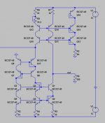
It is imho far better to use a current conveyor, or more colloquial "current buffer" instead. It could be as simple as one single transistor, connected in common base (or common gate), driving into a resistor of sufficiently high value to achieve the desired voltage.
qusp has proven that with a single MOSFET (wasting loads of power though), Nelson Pass with a complementary JFET-pair and Jocko with bipolar transistors. My own single-ended circuits achieve better than -90dB THD at 0dBfs with common +-15V supplies.
The circuit in #3 is a more elaborated complementary Version.
The conveyor is used to present the DAC output a low enough impedance so it can work into optimum load conditions. The conveyor simply passes the input current either 1.1 to its output, or mirrors the input current 1:1. A resistor is connected at the conveyor´s output, converting the current into a voltage.
Since the CB or CG circuit is extremely fast and without feedback, it can follow the current steps of the DAC with ease. Only a small cap in parallel to the IV-resistor is needed to bandwidth limit for Freqs >500kHz. With high clocked DACs there´s no need at all for additional analog post filtering. The digital filters inside the DACs achieve more than enough stopband attenuation nowadays.
The signal voltage may then be buffered to drive the connected load device.
The conveyor has the big advantage, that the value of the IV-resistor may be as large as one can think of. In theory up to infinite, but there are of course practical issues. The achievable signal voltage values may be so large though, that one could drive loudspeakers if only a sufficiently powerful buffer is used.
jauu
Calvin
the problem with passive IV is, that due to the small required resistor value, the resultant voltage swing needs voltage amplification of app. +20dB.
It is imho far better to use a current conveyor, or more colloquial "current buffer" instead. It could be as simple as one single transistor, connected in common base (or common gate), driving into a resistor of sufficiently high value to achieve the desired voltage.
qusp has proven that with a single MOSFET (wasting loads of power though), Nelson Pass with a complementary JFET-pair and Jocko with bipolar transistors. My own single-ended circuits achieve better than -90dB THD at 0dBfs with common +-15V supplies.
The circuit in #3 is a more elaborated complementary Version.
The conveyor is used to present the DAC output a low enough impedance so it can work into optimum load conditions. The conveyor simply passes the input current either 1.1 to its output, or mirrors the input current 1:1. A resistor is connected at the conveyor´s output, converting the current into a voltage.
Since the CB or CG circuit is extremely fast and without feedback, it can follow the current steps of the DAC with ease. Only a small cap in parallel to the IV-resistor is needed to bandwidth limit for Freqs >500kHz. With high clocked DACs there´s no need at all for additional analog post filtering. The digital filters inside the DACs achieve more than enough stopband attenuation nowadays.
The signal voltage may then be buffered to drive the connected load device.
The conveyor has the big advantage, that the value of the IV-resistor may be as large as one can think of. In theory up to infinite, but there are of course practical issues. The achievable signal voltage values may be so large though, that one could drive loudspeakers if only a sufficiently powerful buffer is used.
jauu
Calvin
driving Cload doesn't have much to do with feedback caps if you're not using noise gain input C to gnd too, the negative input "virtual gnd" really isn't real gnd
in fact the OPA6132 datasheet has an example with 1 nF feedback C
not knowing the DAC Iout Z can't really say if it would work but the reasoning should be kept straight
"Driving cload" was an oversimplification, you're right. Still, feedback caps seem best avoided with opa1632 in I/V. (cfr http://www.diyaudio.com/forums/twisted-pear/128137-buffalo-dac-ess-sabre-9008-a-181.html#post1811726 )
Hi,
Sergio, I like to keep things simple. As such I prefer the single-ended common base schematic with current sourcing DACs like the PCM179x.
I1 may be a simple single N-JFET current source (still lowest in noise compared to more complex and more stable ccs)
D1 may be a second bipolar connected as Diode. In fact Q1/D1 is best chosen a Dual for thermal tracking of the signal current injection point.
With Riv connected to teh supply line, the quality of the supply needs to be high, since the positive PSRR is 0. The Jocko is better in this regard, but the active current source introduces some noise and I never managed to get much better than -60dB THD at 0dBfs, some 20-30dB worse than the passive solution.
Both require a DC-blocking cap or a level translator towards the output.
The Bakuun and folded cascode may omitwith DC-caps at the cost of more complexity and noise and probabely no better THD than the Jocko.
Q1,2,3 and Q5 may be replaced by JFETs for better THD, due to Gate-leakage beeing lower than Base-current, but input impedance may be higher than with bipolars.
Surfing the CFP-train at the time, I will look into te possibility of CFP-ing the conveyor-transistor again. Tried that a couple of years ago, but somehow lost interest. See also AES reprint 4326(B-1), 101st Convention, Los Angeles, Nov 8-11, 1996 "Low Input Impedance Current-to-Voltage Conversion Circuit for Current-Output Digital-to-Analog Converters", Michael Smedegaard
jauu
Calvin
Attachments
Hi,
the problem with passive IV is, that due to the small required resistor value, the resultant voltage swing needs voltage amplification of app. +20dB.
It is imho far better to use a current conveyor, or more colloquial "current buffer" instead...
Hi, Calvin,
Current conveyor circuits have drawbacks as well. For example, unless such a circuit utilizes some local or global feedback loop to attain low distortion I/V conversion, the conveyor bias current needs to be quite high relative to the peak signal current, maybe by a factor of ten. This also places significant and broadband dynamic current demands upon the local regulators supplying the current conveyor. In addition, some of the best current output DAC chips (PCM179x and AD1955) need to source or sink their own D.C. bias currents in to a current conveyor, which could severely upset the circuit operating symmetry if not offset by some matched complementary secondary current source or sink.
Those implementation concerns keep pushing me away from current conveyors (despite my appreciation for their conceptual logic) and back to an low value passive resistor I/V, followed by simple passive low-pass filtering, followed by active open-loop voltage amplification.
Last edited:
Hi, Calvin,
Current conveyor circuits have drawbacks as well. For example, unless such a circuit utilizes some local or global feedback loop to attain low distortion I/V conversion, the conveyor bias current needs to be quite high relative to the peak signal current, maybe by a factor of ten. This also places significant and broadband dynamic current demands upon the local regulators supplying the current conveyor. In addition, some of the best current output DAC chips (PCM179x and AD1955) need to source or sink their own D.C. bias currents in to a current conveyor, which could severely upset the circuit operating symmetry if not offset by some matched complementary secondary current source or sink.
Those implementation concerns keep pushing me away from current conveyors (despite my appreciation for their conceptual logic) and back to an low value passive resistor I/V, followed by simple passive low-pass filtering, followed by active open-loop voltage amplification.
Yeah, I played around with symmetrical complementary current conveyors in simulation ad nauseum, and not only did they have poor PSRR, as Ken said the bias current of the DAC requires some kind of additional compensation, otherwise the circuit is completely knocked off balance. Another drawback is the requirement for matched parts in any discrete complementary arrangement.
I tried zero field input transformer I/V circuits as well, but the transformer always adds substantial distortion.
I've settled on the normal opamp based I/V converter myself, though I am intrigued by the use of a THAT 1200 as an instrumentation amplifier in this kind of circuit.
To each their own, as they say.
- Status
- This old topic is closed. If you want to reopen this topic, contact a moderator using the "Report Post" button.
- Home
- Source & Line
- Digital Line Level
- Current differential to voltage line level from PCM1794 et al