Didn't see the impedace of the negative input. 2/3 of RG = 667RI think i found the answer to the input imp question in:
http://www.ti.com/lit/ds/symlink/lmh6554.pdf section 9.2.2. RIN = 2RG = 2 * 1K = 2 K. So it is maybe some room for lower resistors if noise is still an issue.
Overlooking the obvious: the input impedance of a difference amplifier - Precision Hub - Blogs - TI E2E Community
Or does it not apply to fully differential amps?
Hi Sterlingimages,")
Might I get you to look also at THAT chips also I used a THAT1512 IIRC to do the outputs for my dcx ,I converted with these because it was said they mimic a transformer type sound signature,
I layed out the boards almost as pictured on THAT's website,only a few parts and a volume control integral to the chip,sweet just what I needed a pre and a volume control,and I think it sounds very good,butt you listen I'm not going to fill you with all those words of grandeur about it's sound,
I did raise the input R and I have a 3vpp output which I drive 2 F5's tweeter single in.All the rest is balanced 4Aj's for upper mids and low mids, and a QSC to drive 2 of Xoc's 18" subs
They do have some very good spec sheets and some examples of best configurations.
Good luck,Happy listening!
NS
Attachments
Hi,
Would you post up if you get a board?
I use a heat gun to pre warm and also to remove parts from smd boards and a hot plate works also,I just warm it up till it 's hot and drop a few solder beads with flux and wait till they disappear,lots ezier than a iron,I have a hot air machine on it's way I have no experience with it yet but it will remove LSI chips so I hope it will do some smaller parts with ease,be cautions with the heat gun as not heat the whole area, parts will loosen and move ,I have only had that happen once,I hope the smaller nozzle on the hot air hand piece will solve that problem.
NS
It's been a while.
Over the past holidays I finally managed to complete this project – after an initial setback with the voltage regulators (Owen ranted about it already, so I don't have to).
This was the first time I worked with solder paste and a hot air reflow station.
It was a great learning experience!
In my opinion this project can easily be completed using proper hand soldering skills - as long as the voltage regulator section is omitted (and bypassed as described in the BOM and schematic).
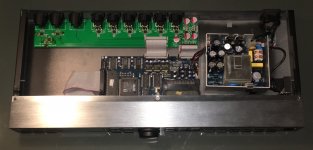
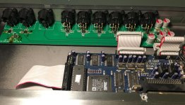
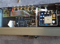
I've taken a couple of quick snapshots.
You can see that I reworked the input section by hand.
This was due to an excess of solder paste underneath one of the devices - a mistake that cost me one OPA1632, one LME49990 and one TPS7A4100.
It's working now!
Cheers,
Sebastian.
PS:
For working with QFN packages I really recommend a stencil, though.
Should I do this repeatedly, I'd order myself a universal stencil with different SMD IC patterns to paste the difficult ICs separately (which I will probably end up doing, seeing that the ability to work with tiny SMD packages opens up the world of modern parts).
Maybe this is even a good idea for group buys: A mylar stencil with just the QFN pattern (panelized) - separated into single pieces - would cost less than a dollar per DIYer.
The only way I could justify the learning curve via trial-and-error is by going through a stash of free samples from TI.
Over the past holidays I finally managed to complete this project – after an initial setback with the voltage regulators (Owen ranted about it already, so I don't have to).
This was the first time I worked with solder paste and a hot air reflow station.
It was a great learning experience!
In my opinion this project can easily be completed using proper hand soldering skills - as long as the voltage regulator section is omitted (and bypassed as described in the BOM and schematic).
I've taken a couple of quick snapshots.
You can see that I reworked the input section by hand.
This was due to an excess of solder paste underneath one of the devices - a mistake that cost me one OPA1632, one LME49990 and one TPS7A4100.
It's working now!
Cheers,
Sebastian.
PS:
For working with QFN packages I really recommend a stencil, though.
Should I do this repeatedly, I'd order myself a universal stencil with different SMD IC patterns to paste the difficult ICs separately (which I will probably end up doing, seeing that the ability to work with tiny SMD packages opens up the world of modern parts).
Maybe this is even a good idea for group buys: A mylar stencil with just the QFN pattern (panelized) - separated into single pieces - would cost less than a dollar per DIYer.
The only way I could justify the learning curve via trial-and-error is by going through a stash of free samples from TI.
Attachments
Hi Sebastian,
Awesome work! The board looks very good, and you actually managed to get the regs up and running as well. Kudos!
A complete stencil absolutely makes building the boards a breeze compared to any other possible method. I'm now in the habit of ordering a proper laser-cut stainless steel stencil when I order any PCB which allows you to select the correct thickness for the solder paste, and paste up an entire board in a matter of minutes, including setup. From there, you just drop on the parts and bake.
It would definitely be nice to include a mylar stecil with each board, but I have not yet found a reasonable priced source for these. The stainless full frame stencils cost between $75 and $100 so they make sense if you're doing more than just a few boards. They definitely don't make sense if you're only doing one board, unless you start shipping them about to everyone, but the logistics and shipping costs become unreasonable.
I also love your solution to the power connector with the 90 degree pin header. I put that cap too close (didn't account for the bulgy sides of the mating connector, and this is a much more elegant solution than bending the cap over! I can't believe I didn't think of this, and instead spent like 2 hours searching for a narrower edged connector which doesn't exist
How do you find it sounds and works compared to the original?
Regards,
Owen
Hi Owen,
Thanks. The beauty of reflow soldering. But the reworked part really took a lot of botching to get right. Speaks for your choice of PCB manufacturer, this board took any abuse I exposed it to!
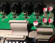
I used OPA1632 in the input section and THS4130 as output devices, as that was what I had available.
I think it has been established that these devices can be considered equivalent.
Well, I had it fully running once (before causing a short by way of a hidden solder bridge).
The positive regulator is thus still fried (and currently bypassed), I will rework it as soon as fresh flux gel arrives in the mail.
This makes for an interesting side effect: the OPA1632s' Vocm lies at supply midpoint, which is currently ca. +1.5V = 1/2 * (-12V + 15V), as is to be expected by the function of the fully differential opamps.
Which is why I currently cannot use the board with my active speakers of choice (since they still have asymmetrical inputs).
I wonder why that has to be.
You leave the Vocm pin floating.
Is there any particular reason (safety, noise, performance) why you don't have them tied to GND (0V)?
The THS4130 datasheet (p. 15f) certainly has no problem recommending it.
I assume 25$ for a 100mm x 100mm mylar stencil, good enough for a couple of uses.
Placing a 10 by 10 matrix of QFN footprints could yield 100 copies.
Cutting this up and shipping one 10mm x 10mm copy together with every board would make 100 DIYers happy for 0.25$ each.
That also got me. I had the straight version soldered in already, only to then recognise that you never actually show a connector plugged in there...
I desoldered the straight one and just got an angled one instead (Digikey # 609-3338-ND).
Maybe a recommendation for an updated version of the BOM – together with a correction to the quantity of 1k resistors (16 instead of 12, recognise the Mini-Melf types at the input of my board?).
There's also the leftover ADM7150 section in the schematic that had been noted before.
From what I've heard – going directly into a Hypex UCD400 – it's an immediate improvement. The sound is as clear as it should be.
It worked flawlessly the first time I actually hooked it up completely: power-up, muting, unmuting, power-down – all as expected.
At the same time, it's absolutely revealing about the flaws of the actual DCX main board. Mine is unmodified, so it uses the original voltage regulators and bypassing. That has to be addressed soon!
Cheers,
Sebastian.
PS:
Please note the fully recapped SMPS. I'm getting there.
The board looks very good
Thanks. The beauty of reflow soldering. But the reworked part really took a lot of botching to get right. Speaks for your choice of PCB manufacturer, this board took any abuse I exposed it to!
I used OPA1632 in the input section and THS4130 as output devices, as that was what I had available.
I think it has been established that these devices can be considered equivalent.
and you actually managed to get the regs up and running as well. Kudos!
Well, I had it fully running once (before causing a short by way of a hidden solder bridge).
The positive regulator is thus still fried (and currently bypassed), I will rework it as soon as fresh flux gel arrives in the mail.
This makes for an interesting side effect: the OPA1632s' Vocm lies at supply midpoint, which is currently ca. +1.5V = 1/2 * (-12V + 15V), as is to be expected by the function of the fully differential opamps.
Which is why I currently cannot use the board with my active speakers of choice (since they still have asymmetrical inputs).
I wonder why that has to be.
You leave the Vocm pin floating.
Is there any particular reason (safety, noise, performance) why you don't have them tied to GND (0V)?
The THS4130 datasheet (p. 15f) certainly has no problem recommending it.
It would definitely be nice to include a mylar stecil with each board, but I have not yet found a reasonable priced source for these.
I assume 25$ for a 100mm x 100mm mylar stencil, good enough for a couple of uses.
Placing a 10 by 10 matrix of QFN footprints could yield 100 copies.
Cutting this up and shipping one 10mm x 10mm copy together with every board would make 100 DIYers happy for 0.25$ each.
I also love your solution to the power connector with the 90 degree pin header. I put that cap too close (didn't account for the bulgy sides of the mating connector, and this is a much more elegant solution than bending the cap over!
That also got me. I had the straight version soldered in already, only to then recognise that you never actually show a connector plugged in there...
I desoldered the straight one and just got an angled one instead (Digikey # 609-3338-ND).
Maybe a recommendation for an updated version of the BOM – together with a correction to the quantity of 1k resistors (16 instead of 12, recognise the Mini-Melf types at the input of my board?).
There's also the leftover ADM7150 section in the schematic that had been noted before.
How do you find it sounds and works compared to the original?
From what I've heard – going directly into a Hypex UCD400 – it's an immediate improvement. The sound is as clear as it should be.
It worked flawlessly the first time I actually hooked it up completely: power-up, muting, unmuting, power-down – all as expected.
At the same time, it's absolutely revealing about the flaws of the actual DCX main board. Mine is unmodified, so it uses the original voltage regulators and bypassing. That has to be addressed soon!
Cheers,
Sebastian.
PS:
Please note the fully recapped SMPS. I'm getting there.
Last edited:
I have added 3boards of ES9023 DAC (which is sold as I2S Raspberry Pi compliant).
Sold by Audiophonic or TerraDAC in eBay at US$10 or so per board.
They are are connected to BCLK / LRCLK / Serial Data #1/2/3 (for 3way Low / Mid / High) from the mainboard DAC chip pins.
They are working well.
You may add 5V external power supply for these additional 3 DAC boards.
Modify Analog board is quite difficult as the parts are surface mounted devices and very small , so hard for old man's eyes!
I know
if you improve all of these, you can be satisfied with DCX2496.
- power supply circuits on DCX2496,
- replace with good Xtal for DSP ,
- change analog OP amps gain for consumer level compliant
(lowering gain for adequate level and distortion for consumer amps)
My way is easy way , ES9023 chip does not require MCLK ,only BCLK
and LRCLK (and data).
You may get better sound even if you only add these boards without
other modifications.
Yutaka IIDA,AEDIO Japan
About USB input most easy way is,
(1) Use Amanero Combo 384 board as USB interface
Amanero is USB Audio Class 2.0 compliant.
(2) User resampler in foobar2000 or mpd on Raspberry PI(Volumio) (sox or soxr).
(3) Add +5V power supply and this daughter board on Amanero.
Italy Amanero USB DSD coaxial output module daughter card | eBay
Then adding driver software (Win) if required,
you can use DCX2496 with foobar2000 /Win , MacOS or Raspbian / Volumio2
Now I am planning to add this boards to get DCX2496 SPDIF out and
WM8805 I2S to SPDIF Coaxial Output Module support CD Player 44.1K 48K 96K ~ 192K | eBay
use with STA326 based digital input amps (crazy idea?) such as,
Finished STA326 50W+50W OLED 2.0 Class D AMP Amplifier Board
This amps can be used with AES-16 with SPDIF converter with foobar2000 / our own FIR linear phase active crossover plug-in( Down load from file ).
Yutaka IIDA,AEDIO Japan
DCX2496 PGA2311:
Some years ago, I did a different things but with volume controlled
SDF
Oh, please, can I play?
I just finished last week AMB Kappa DCX by nycavsr2000 | Photobucket
Password is: KappaDCX
Please ignore the fancy resistors
...they looked too good to leave in the box, who cares if they sound good or not, it's just money Best,
Anand.
DCX analog board
[Hi
Is it possible to buy 2 of These boards, you can send it to a friend of mine in the USA, do you supply a partslist with it?
Regards, Tom.
QUOTE=opc;4424643]Hi Brett,
I've got a pile of 38 boards sitting beside me now
If you already have the OPA parts then it's a bit of a no-brainer. Build costs would basically be just the PCB, a few passives and two connectors.
I'll be putting the boards up for sale tomorrow using my usual PCB sign up sheet. They'll be $30 each. I'll add the info to my Wiki page tomorrow as well (schematic and BOM).
Regards,
Owen[/QUOTE]
The standard DCX2496 output is +22dBu = 9.75Vac
2Vac from a single opamp needs supply rails above 6Vdc (+-3Vdc)
6Vac from a single opamp needs supply rails above 18Vdc (+-9Vdc)
But the balanced signal from two opamps reduces the requirement to 3Vac from each opamp, requiring supply rails above 9Vdc (+-4.5Vdc).
2Vac from a single opamp needs supply rails above 6Vdc (+-3Vdc)
6Vac from a single opamp needs supply rails above 18Vdc (+-9Vdc)
But the balanced signal from two opamps reduces the requirement to 3Vac from each opamp, requiring supply rails above 9Vdc (+-4.5Vdc).
What is the latest info on purchasing the DCX PCBs? I added my name to the list many months ago, but never received any response from Owen "OPC." Tried PM-ing him a few times....NO answer.
He is apparently WAS still active and monitoring this thread, as he posted here in January 2017 about another person's build. He last posted February 13th 2018 on another thread regarding his Wiki with info for ordering all of his PCBs. I'm hoping he is still around!
Owen...can you please let us know current status of the PCB??? I'd like to buy one. Thanks,
Last edited:
- Status
- This old topic is closed. If you want to reopen this topic, contact a moderator using the "Report Post" button.
- Home
- Source & Line
- Digital Line Level
- DCX2496 Upgrade Board - Objectively Tackling the Improvement of a Stock DCX2496