For experimental clocks or XOs, I want to put a "load" in front of it (w/o using intended ICs such as DACs or decoders). In other words, I want the clock to behave as it were in situ of its normal topology.
How does one effectively/cleanly load the clock using simple/passive components? E.g, via resistor, cap, etc. on the clock output.
The result of such an experimental setup should be some sort of breadboardable ckt that can be easily part-swapped (tweaked) whilst on the oscilloscope.
Thx!
How does one effectively/cleanly load the clock using simple/passive components? E.g, via resistor, cap, etc. on the clock output.
The result of such an experimental setup should be some sort of breadboardable ckt that can be easily part-swapped (tweaked) whilst on the oscilloscope.
Thx!
For both you have to take into account the PCB parasitics especially, or if using cable the cable impedance mismatches etc. The best way of doing this is using high speed simulation software, then the clock and any terminating resistors can be modeled to match the real life conditions, otherwise any results are pretty meaningless.
This may be overcomplicating things ... at least for the time and effort I want to put into a projectFor both you have to take into account the PCB parasitics especially, or if using cable the cable impedance mismatches etc. The best way of doing this is using high speed simulation software, then the clock and any terminating resistors can be modeled to match the real life conditions, otherwise any results are pretty meaningless.
")
Another way to "model" this is to know what the "nominal" input impedance of the X_in (clock input pin) may be. Anyone want to take a shot?
Using a simple clock
One can't easily tweak/prototype in and around PC cards so that's why I need an on-the-bench/breadboard solution.
Nothing fancy. I've got to keep the design simple and as compact as possible as it will occupy some tight real-estate. Namely, for use w/ PC sound cards (see Xonar ST thread elsewhere). I have 12v avail from Molex. I was thinking something like this...Loading the oscillator is clearly a much simpler problem than designing the oscillator, so I wonder what sort of experiments you are planning.
One can't easily tweak/prototype in and around PC cards so that's why I need an on-the-bench/breadboard solution.
Nothing fancy.
Unfortunately I doubt that anything less than fancy will suffice.
The result of such an experimental setup should be some sort of breadboardable ckt that can be easily part-swapped (tweaked) whilst on the oscilloscope.
I fear that anything 'breadboarded' is likely to suffer from problems due to strays and other inconsistencies which will make any results meaningless in terms of true high performance.
If I were embarking on such an investigation I would anticipate needing well designed PCBs and highly repeatable conditions to evaluate component changes. I would expect to iterate the PCB more than once and see differences due to those changes alone.
A test setup capable of revealing meaningful differences in jitter at the levels which are the current SOTA will not be cheap, it is beyond the capabilities of the average 'scope. You need a lot of resolution, storage, and a software suite purposed to the task. You might alternatively test in situ but that would require a dedicated audio test set, such as the Audio Precision, and completely respinning the target board to accommodate the changes.
Having routed many many clocks, the only guaranteed way is simulation, you can then match any termination required to the actual PCB and hence get the best integrity of the clock signal, that is if you want ultimate fidelity of the clock signal, and when distributing a clock it becomes a necessity. A lot of the ad-hoc modifications I see on here to clocks will cause more problems than they solve.
The basic rules for clocks (any) are short traces, as short as humanly possible, isolation from noise, and avoid any cables or traces that create an integer divideable fraction of the wavelength (again the wavelength is determined by the layout and the dailectrics used, whether the route is microstrip or stripline etc etc), 1/10 1/20 1/4 1/2 avoied like the plauge.
The basic rules for clocks (any) are short traces, as short as humanly possible, isolation from noise, and avoid any cables or traces that create an integer divideable fraction of the wavelength (again the wavelength is determined by the layout and the dailectrics used, whether the route is microstrip or stripline etc etc), 1/10 1/20 1/4 1/2 avoied like the plauge.
For audio purposes about the only thing that matters is jitter, but that is hard to measure and depends far more on oscillator design and crystal quality than external loading. If you are worried about loading then you can always add a buffer.
I still don't know what you intend to do. I suspect you don't know either.
I still don't know what you intend to do. I suspect you don't know either.
Again this can be affected by the layout. Buffers can be even more of a nightmare, the drive current can be quite hard causing ringing and other problems and often require more careful matching than an unbuffered clock.
But most of this is moot unless you are going for the ultimate in clock signal fidelity as equipement usually works, and as we often dont have the tools to measure it can imagine these beautiful clock signals traveling down a few inch of wire and improving everything...
Excuse my cynicism.
Oh if you want to find out the loading (real) a device presents you are probably better of getting hold of the IBIS data for a device.
Vanguard tcxo oscillator in PC
Thx for your inputs .... stuff to think about.
As far as the experiment ... i.e, what do I REALLY want to do?
Simply: Deliver clean power to a Vanguard tcxo oscillator.
Something a bit better than this:
Remember this is for a PC. And pulling that audio card out to tweak -- never mind trying to stick a probe on it in situ -- is not ... uh ... convenient
I'm not looking for SOTA clock performance. I'll even be willing to not 'scope the output of the XO if my scope is not up to the task. Rather, I could take scope measurements as far as the PSU/reg output -- tweaking that part of the ckt as much as possible. The XO I have is 0.1ppm Vanguard TCXO, which others have favorably commented on. The simple Tent ckt from #6 (above) is also okay for me -- I've used it before.
Still, for tweaking purposes, methinks the XO should feed something on its OUT pin. How about something as simple as ,say, a 10pf poly cap + resistor ... to ground?
Thx for your inputs .... stuff to think about.
As far as the experiment ... i.e, what do I REALLY want to do?
Simply: Deliver clean power to a Vanguard tcxo oscillator.
Something a bit better than this:
An externally hosted image should be here but it was not working when we last tested it.
Remember this is for a PC. And pulling that audio card out to tweak -- never mind trying to stick a probe on it in situ -- is not ... uh ... convenient
I'm not looking for SOTA clock performance. I'll even be willing to not 'scope the output of the XO if my scope is not up to the task. Rather, I could take scope measurements as far as the PSU/reg output -- tweaking that part of the ckt as much as possible. The XO I have is 0.1ppm Vanguard TCXO, which others have favorably commented on. The simple Tent ckt from #6 (above) is also okay for me -- I've used it before.
Still, for tweaking purposes, methinks the XO should feed something on its OUT pin. How about something as simple as ,say, a 10pf poly cap + resistor ... to ground?
Last edited:
Short traces vs. speed of "light"
Is this because the of shorter travel time (even at or near c) is important given the scale of clock pulses ... and/or ...because the addit. trace/wire/etc. picks up noise?The basic rules for clocks (any) are short traces, as short as humanly possible, ....
Both, for a fun view of the problemm from the other side of the coin have a look at this:
The 10 Best Ways to Maximize Emission from Your Product
Basicly the clock is the most important signal, all other timing events are controlled by this signal, the longer the trace, as you have said the more likely it is to pick up noise, pollute other signals, have impedance mismatches, ISI (inter symbol interference), the loop area is bigger etc etc.
if you are routing clocks on a PCB thenthe spacing round a clock should be 3S min, where S is the normal track to track spacing, this allows you to run a guard track round the clock signal.
The following link shows a good example of impedance mismatch on your clock signal, and some other graphical examples of what happens to the poor clock signal when badly treated:
http://www.digikey.co.uk/Web Export/Supplier Content/CTS_8006/PDF/CTS_AN1025.pdf?redirected=1
The above photograph is a good example of how not to do it, while the clock connection might be short we have an ariel fastened to the VCC pin, and by the looks of it no local decoupling.
Remember the clock is queen, the king being 0Vs (GND return)
The Velocity factor of any signal is found by Vf=1/Sqare Root of Er. (approx 4.2 for FR4, outer layer traces the signal propogates faster than inner layer traces, a factor to remember when doing length matching).
Trace length should only be increased when required such as DDR interfaces where it has to be in relation to the longest data and address lines, for standard clocks always minimise the distance. More boards fail EMC due to clock routing and length than almost any other cause, this noise will also effect the signals on the actual PCB its self. EMC and signal integrity are two sides of the same coin.
Trace length should only be increased when required such as DDR interfaces where it has to be in relation to the longest data and address lines, for standard clocks always minimise the distance. More boards fail EMC due to clock routing and length than almost any other cause, this noise will also effect the signals on the actual PCB its self. EMC and signal integrity are two sides of the same coin.
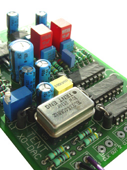
I think the tight real-estate in PC cases and the SC naturally force one to use short paths. The OUT pin of this osc. is essentially at the decoder pin:
BTW: Found what I may have been querying about (it was on the eBay sale page for the Vanguard osc!):
An externally hosted image should be here but it was not working when we last tested it.
BTW: Found what I may have been querying about (it was on the eBay sale page for the Vanguard osc!):
An externally hosted image should be here but it was not working when we last tested it.
Hi,
Have you please a link for the simulation software you talk about ?
Can this scheme upon (page 1) from Tentslab website may be use with two outputs (Masterclock) ?
Do we have to use a buffer if one of the load is not near the XO (few inches to the source : streamer or cd player) ? (one output buffer near the XO and one input bufer near the load?)...after reading your two interesting links, it seems to be impossible to reclock better a ready made device without a lot of ressources (pcb design, measurement) !
Last edited:
External clocking and reclocking
...with a re-clocker (buffer) ckt, and it did improve SQ despite the added complexity (= greater trace mileage, etc.). I view a dedicated (outboard) clock/re-clocker as necessary evil: perhaps, two steps bwd and three fwd.
Search for 'XO clock' within diyaudio.com and you'll come up with several hits. I've made something similar to Tent's XO-DAC clock here ...Can this scheme upon (page 1) from Tentslab website may be use with two outputs (Masterclock) ?
Do we have to use a buffer if one of the load is not near the XO (few inches to the source : streamer or cd player) ? (one output buffer near the XO and one input bufer near the load?)...after reading your two interesting links, it seems to be impossible to reclock better a ready made device without a lot of ressources (pcb design, measurement) !
...with a re-clocker (buffer) ckt, and it did improve SQ despite the added complexity (= greater trace mileage, etc.). I view a dedicated (outboard) clock/re-clocker as necessary evil: perhaps, two steps bwd and three fwd.
The one I use:
CADSTAR Signal Integrity Verify
another
Signal Integrity Analysis, Design & Simulation Tools | HyperLynx® - Mentor Graphics
Cadences offering:
Cadence Allegro PCB SI
and just for fun:
AC/DC Module | Simulation Software
CADSTAR Signal Integrity Verify
another
Signal Integrity Analysis, Design & Simulation Tools | HyperLynx® - Mentor Graphics
Cadences offering:
Cadence Allegro PCB SI
and just for fun:
AC/DC Module | Simulation Software
Hello hollowman,
A couple of people here &elsewhere have posted on several occasions a caveat concerning these tall-ish looking TCXOs (marketed by some chinese sellers as "low jitter" - they're quite the opposite). Inside you will find 2 pcbs: one containing a pullable VCXO at 19.2MHz or 19.8MHz most likely with a TC compensating network on the control pin; the other having a PLL multiplier circuit like the one linked in this post
...You have already two reasons why it can't be low-jitter. Luckily some professionally made measurements of these contraptions can still be found somewhere on the forum where you're no longer a member.
Best luck with your project.
I think the tight real-estate in PC cases and the SC naturally force one to use short paths. The OUT pin of this osc. is essentially at the decoder pin:
An externally hosted image should be here but it was not working when we last tested it.
BTW: Found what I may have been querying about (it was on the eBay sale page for the Vanguard osc!):
An externally hosted image should be here but it was not working when we last tested it.
- Status
- This old topic is closed. If you want to reopen this topic, contact a moderator using the "Report Post" button.
- Home
- Source & Line
- Digital Line Level
- XO clock "load"