tried using 300v 330uf computer cap for output of lm317- insane dynamics and cleanness. sound was a bit bright so i bypassed with an oiler and it now sings the best music i have heard yet. this experience makes me realize that 'audio-grade' caps are all bogus ")
for the lm317 im using 10000uf smoothing cap, 10uf adjust to gnd, and 200ohm R1. i was fiddling with 1000uf output cap for a while but it kept burning out something to where the chips would only buzz.
for the lm317 im using 10000uf smoothing cap, 10uf adjust to gnd, and 200ohm R1. i was fiddling with 1000uf output cap for a while but it kept burning out something to where the chips would only buzz.
Last edited:
could somebody help me figure out how this happened?
the ground wire between the ddc and the 1543 burned through the sleeve.
battery was left to overcharge on 1/4th ampere walwart for days...
both the receiver and dac chip and decoupling cap is lovingly shielded in copper *sob.
the dac still works, btw.
also the amp might be dc coupled and the dac was, too. *obviously i handed this over to someone else and the damage was caused on his terms...
the ground wire between the ddc and the 1543 burned through the sleeve.
battery was left to overcharge on 1/4th ampere walwart for days...
both the receiver and dac chip and decoupling cap is lovingly shielded in copper *sob.
the dac still works, btw.
An externally hosted image should be here but it was not working when we last tested it.
also the amp might be dc coupled and the dac was, too. *obviously i handed this over to someone else and the damage was caused on his terms...
Last edited:
i keep burning out chips after chip on my tower 1543 setup. not literally smoke and fire but some of them just go mute or make nothing but static/hum. this happens to both 317 regulator and zener reg setup and the pitiful thing is i have them soldered 10 in a tower so troubleshooting individual chip becomes almost torture.
i have an extremely poor layout so i'd like to know what kind of scenario would cause damage to the chips in case of a poor layout. thanks.
p.s. when they do work they make the most glorious sound. the recipe i have now is 10000uf smoothing cap, 1000uf output cap for lm317 with 1uf< bypass.
i have an extremely poor layout so i'd like to know what kind of scenario would cause damage to the chips in case of a poor layout. thanks.
p.s. when they do work they make the most glorious sound. the recipe i have now is 10000uf smoothing cap, 1000uf output cap for lm317 with 1uf< bypass.
i keep burning out chips after chip on my tower 1543 setup. ...
i have an extremely poor layout so i'd like to know what kind of scenario would cause damage to the chips in case of a poor layout. thanks.
Could be transient overvoltage spikes on the power supply when you turn it on or off. Maybe use a Zener diode rated for 7VDC (IIRC the TDA1543 chip can take up to 8VDC) to clamp the supply line.
Maybe the input digital signals have transients? A buffer chip on the same board close to the TDA1543s may prevent the blowouts. A 74S32 AND chip would be one, or a 74S04 inverter (with two sections in series to uninvert the signals). This would lessen the load of 8 DAC chips on the I2S lines as well. And having the analog output amp/buffer on the same board should also help. Having a good ground plane should help the layout. A ground plane could be created by making a mesh of ground wires on your board.
I've played with TDA1543 chips as well, see my page Modifying CD player DAC circuits
Thx wa2ise, i also suspect the transformer had something to do with it, since the damage is moslty caused.by one brand of transformer. s there more graceful way than adding a zener reg? Id think it would impact the sound quality. And up to how many chips do you suppose are damaged from it? Id like to salvage whatever i can.
hi piotr i am in favor of the te8802 baord. Though its not as refined as xmos, the tonality is more dense (coloration?) And with a battery supply it sounds smoother than xmos. So for the price i think its the.best deal there is.
hi piotr i am in favor of the te8802 baord. Though its not as refined as xmos, the tonality is more dense (coloration?) And with a battery supply it sounds smoother than xmos. So for the price i think its the.best deal there is.
Wa2ise i also like your tube circuits. Ill probably try yours or http://www.diyaudio.com/forums/digital-line-level/236520-nos-dac-tube-buffer-output.htm after the differential one.
Also im only using one diode for half wave rectification since this sounds better to me, but could this be the cause of the frequent overvoltage?
Also im only using one diode for half wave rectification since this sounds better to me, but could this be the cause of the frequent overvoltage?
Last edited:
Thx wa2ise, i also suspect the transformer had something to do with it, since the damage is mostly caused.by one brand of transformer. s there more graceful way than adding a zener reg? Id think it would impact the sound quality.
Also im only using one diode for half wave rectification since this sounds better to me, but could this be the cause of the frequent overvoltage?
The zener would normally do nothing, sitting across the power supply. It would only conduct if the power supply voltage gets too high. It's similar to a crow bar protect circuit.
Also be sure to more securely mount the various connections. You might be having some connection momentarily touching something else, and that causing the blowouts?
I doubt that the half wave rectification would be the problem. Though a bridge rectifier would make for less ripple, and load the power transformer better. Less DC imbalance on it.
Last edited:
i know a simple zener regulator is about the most primitive thing you could use for a dac but short of salas shunt, it's the best sounding thing i have tried yet. consider that the chip only draws 60ma max, a 5w zener would have a plenty of room before distortion and the listening test clearly shows that it is so. the zener sounds even better than an8006 in all parameters. having messed around with ecdesign's circuit some more recently, i've come to try separate zener supplies for all 3 voltages, 8.2 for the chip, 8.2 for resistor bias (i don't know the calculation but it's definitely higher than 4 and 8.2 was all i had...) and then 2.4 for dc output. result is stunning to say the least. it has better dynamics than my 2 chip 8v setup, and most air and definition i have heard from tda1543 yet.
it's also least colored. i used metal films that i had laying about but something about the circuit makes it so that the resistors don't impart their sound as much. i know, as i should by now, what carbon comp/ film, metal film, and caddock resistors sound with this dac but on john's circuit they don't pollute the tonality as much.
in conclusion my new setup sounds very 'modern' with a touch of analog smoothness. much like a hybrid of r2r/delta sig with best of both worlds except resolution... i fear that can only be had with 1541 or better...
on a side note, i find 2 chip setup at 8v makes a hard disjointed sound much like peter daniels reported way back.
last stop is zener regulated ecdesign circuit in differential mode.
well obviously the dc coupling part of john's circuit has no function in differential mode, but the vref trick i think still is a significant step forward for 1543
Last edited:
hi my best 1543 implementation yet. the ridiculous heatsink and the poor layout resulting from it is needed because the chips are ran at.... 11.5v!
i did peter daniel's differential build to single end connectors (- signal to ground)
sound is reaching the 1541 territory. still aggressive and rounded off but the ambiance retrival and soundstaging is as good as i've heard, and i don't think it could get any more dynamic from a passive output.
more to come if something catches on fire
hi my best 1543 implementation yet. the ridiculous heatsink and the poor layout resulting from it is needed because the chips are ran at.... 11.5v!
Yow.
The spec sheet say 8V absolute max. Oh, they probably designed them to take 9V for a reliability margin, and maybe the process they use to make the chips lately allow some more. I'm surprised any of them survived 11.5V.here's how the whole thing looks. terrible layout, i know. but adding a salas shunt came as an afterthought after realizing what a potential differential setup holds. now it's the best digital sound i have ever heard. still doesn't do nuisance like 1541a but slam and dynamic is on a whole new level.
huge oiler is for the output of lm317 which now powers te8802 board (not in the picture)
smaller oiler is 2uf that bypasses the 330uf 400v blue cap on salas. the oiler also has a .1uf polystyrene bypass.
the chips aren't even lukewarm to the touch immediately after i lift off the heatsink. when they were on 11.5v (i even brought it up to 12 for a minute) the heatsink was only slightly warmer than ambient temp and the finger test at 8v shows that they are doing a reliable job. do you think there's some internal mechanic that can overload at 9v+ or is it just heat dissipation issue that i should worry about? granted the i/v resistors were at peter daniels' 8v values so i couldn't discern much improvement with higher voltage but i am willing to do my next build with correct values for 9 or even 11 if i can figure out the calculation....
screen shot tool
huge oiler is for the output of lm317 which now powers te8802 board (not in the picture)
smaller oiler is 2uf that bypasses the 330uf 400v blue cap on salas. the oiler also has a .1uf polystyrene bypass.
the chips aren't even lukewarm to the touch immediately after i lift off the heatsink. when they were on 11.5v (i even brought it up to 12 for a minute) the heatsink was only slightly warmer than ambient temp and the finger test at 8v shows that they are doing a reliable job. do you think there's some internal mechanic that can overload at 9v+ or is it just heat dissipation issue that i should worry about? granted the i/v resistors were at peter daniels' 8v values so i couldn't discern much improvement with higher voltage but i am willing to do my next build with correct values for 9 or even 11 if i can figure out the calculation....
An externally hosted image should be here but it was not working when we last tested it.
screen shot tool
Last edited:
Hi, everyone.
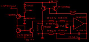
My output stage for TDA1543 with normal, 5 V, power. The circuit creates low impedance to TDA1543, fixed potential in output of 1543 and provides zero DC in self output. It ready to direct connection with transformer. I am using Lundahl LL1527. Sound is excellent.
My output stage for TDA1543 with normal, 5 V, power. The circuit creates low impedance to TDA1543, fixed potential in output of 1543 and provides zero DC in self output. It ready to direct connection with transformer. I am using Lundahl LL1527. Sound is excellent.
Attachments
- Status
- This old topic is closed. If you want to reopen this topic, contact a moderator using the "Report Post" button.
- Home
- Source & Line
- Digital Line Level
- discrete output for single tda1543