I wished they had old school multibit dacs though, then I would look/search for them s/h.
I find it particularly ironic that they don't, given Charles' staunch anti-feedback stance. He lets it under the radar when its hidden inside digital chips

yes I've had an exchange with him where he denies local degeneration is negative feedback, and in the next line, same post, implicitly uses Blackman's Theorem to answer another question
hard to understand the position - is it bald faced lying to keep his marketing message intact?
hard to understand the position - is it bald faced lying to keep his marketing message intact?
844 is already quite linear, yet isnt the best one on measurements. You could either wrap it with feedback (the linear circuit plus mild feedback approach) or make it beefier to accomodate larger current swings as they did in ayre.
Third option is to make it discrete and thus have a control on its current biasing and fanout.
4th option is to implement some distortion management circuitry...
Or just leave it alone and use proper dac with low current swing. Biasing the input current round zero is essential.
Dont forget that with no-nfb thing you have lots of passive filtering options.
Last edited:
Here is a little from the now obsolete AD846 datsheet also can be used as current feedback opamp, seems it was the forerunner to the AD844, also had a TZ type pin 5. but was mainly used for bandwidth limiting compensation or as a low mA output point but they don't say what the output impedance is at that point either, looks to be similar architecture though.
Cheers George
I've seen used AD846 on ebay if they are that desirable.
So, what's left to do with the AD844 circuit? Is someone going to make a PCB for a group buy or something? I'm not sure if I'm interested myself, just curious.
Why would you want a pcb for 8-legged dip device?
Especially with so many options of implementations available?
Then don't do it if you are not interested.
Thinking of trying this after, either from the AD844 TZ pin or from it's output buffer.
If I come from the TZ pin so as not to load it down because it has such a weak output will I have to remove R4 C2 & R6 on the attached buffer?
If I come off the AD844 output buffer I can leave R4, C2 & R6 in place?
Oops think we've gone over this a few weeks back, a little hung over this morning, big night.
Cheers George
Attachments
Last edited:
Hey George,
You're aware of this thread?
DIYHiFi.org • View topic - I/V convertor output buffer
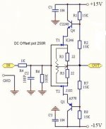
I have these boards as well and I'm getting high dc offset: +50 and +80mV.
How about you?
Using the trimming circuit will give you less offset but the FETs aren't well matched so the performance will suffer.
My upgrade path will be better matched 246/107 FETs then a more full Cascode.
Cheers,
Jeff
You're aware of this thread?
DIYHiFi.org • View topic - I/V convertor output buffer
I have these boards as well and I'm getting high dc offset: +50 and +80mV.
How about you?
Using the trimming circuit will give you less offset but the FETs aren't well matched so the performance will suffer.
My upgrade path will be better matched 246/107 FETs then a more full Cascode.
Cheers,
Jeff
why not use a simple n-Jfet buffer...?? its simple and don't require any matching.
for use with higher current output DAC's it could be paralleled with a high quality resistor to lover the current injection. Not too sure if that would give a noise penalty though. but I will give a distortion benefit, as it sems like the AD844 suffers when the injected current is too high(ish)..
Or you could run mere 844's in parallel to deal with the higher currents. More in parallel would also do away with the need for an output buffer...
I was today thinking of taking the output straight from pin 6 to the output rca's, as I think I have the same gain at this point, and it's supposed to have 80mA drive current at 15ohm output impedance, the only LP filtering I would have is the 1st order at TZ to ground of the 2.7k resistor and 560pf across it which gives -3db at 105khz. Do you guys think I'll be waisting my time with this setup? The PCM1704 is supposed to be glitch free, and maybe it doesn't have too much other noise?
Cheers George
Cheers George
Last edited:
Looks like you've fallen for BB's marketing in their datasheet George. The PCM1704 is only really 'glitch free' around the zero crossing, that's what they state in the details. Since its a co-linear DAC the zero crossing glitches are now occuring at -6dB sinewave amplitude. Besides that its R2R so high glitch across the board compared to segmented current source and resistor string types.
I've got something to tell you guys, but not just yet, I would like to know a little tech stuff that is beyond me at the moment.
You know by that data sheet the AD844 from it's output buffer is able to source up to 80mA from it's 15ohm output impedance, I take it that spec was given by AD with global feedback around the AD844.
Can someone with more knowledge than me tell me what happens to those two figures (do they change and to what) when the AD844 is used without the feedback loop as I am?
Cheers George
Ah yes that abraxalito, missed that.
Well this IC just keeps rewriting the books for me.
I did what most said probably wasn't ideal, I drove the audio output rca's directly from the AD844 buffer with a 47ohm resistor in series just in case, and looked on the scope and yes I did loose about 5% of gain, but I got rid of half of Silicon Valley as well, remember I had a single opamp for LP duty, a dual opamp for balance and single ended duty and a pair of fets for each phase as buffer outputs all after the AD844.
Noise you say? a big fat NO! no more than I had before, in fact a touch less because of the touch less gain, also I still able to hit 2.2v P/P at 0db 1khz from a test disc.
The noise that I watched for was on a 200mhz Teck scope using 400mhz leads, and to boot I cannot see/hear any either at full output.
The sound, yes the sound has taken another leap higher, the sound is just as dynamic rich and all that I said before, but it has become even more relaxing to listen to, yet can still put you through the back wall when needed with it's dynamics, this chip amazes me. I look at it now and think this is as far as I can go with it, then I thought, the guys here aren't too impressed with the output buffer circuit, I got to wondering is it possible to put a little feedback from pin 6 (output) back to TZ (pin 5) just to encase the buffer (sorta local feedback) to maybe make it better?
Cheers George LOVE IT, LOVE IT, LOVE IT!!!!!!!!!!!!!!!!
I got to wondering is it possible to put a little feedback from pin 6 (output) back to TZ (pin 5) just to encase the buffer (sorta local feedback) to maybe make it better?
That would be positive feedback, also known as bootstrapping.
Since this is getting technical, I thought I'd link back to one of the nascent threads from way back in 2006!:
DIYHiFi.org • View topic - "Op-amps unsuitable for audio DAC I/V" - myth?
Holy Heavy Hitters Batman!
Charles Hansen, John Curl, Walt Jung
And the gang!
Jocko, PMA, CarlosFM, Pedja, Elso
Pedja points out:
"Based on the measurements I've done using AD844 open loop I can confirm that there is a problem with its output stage since I've found it adding about 0.5% (at 2V RMS and 1kHz) to the overall open loop THD figure which is quite poor for the diamond buffer, even taking into account relatively low bias current. I hope you can, being the insider, shed more light on the reasons behind. ... "
Walt Jung responds:
"I'm not an insider at ADI, really never was, even when I worked there. Barrie Gilbert designed the AD844.
CFAs with husky outputs can do well, the 811 and 815 come to mind.
Yes, you can run the 844 as a DAC terminator, with roughly a 50R Zin. The current IO of the DAC becomes reflected at pin 5, so an R from 5 to GND recreates a voltage. R > 50R makes for gain. You still need a buffer to drive any useful loads, however."
And more from Walt on pin 5:
"Hello PMA. The buffer at pin 5 of the 844 will be a challenge. I suggest low-C high current xstrs like PN2907A and PN2222A, running the ouput on the warm side (several mA). I'd *not* use the parts spec'd on my website, unless you are really careful. The 2N6715/27 have appreciably higher C than do the above types. See: http://waltjung.org/PDFs/WTnT_Op_Amp_Audio_2.pdf for the general idea. ... "
The link still works!
Walt also mentions PS for CFB opamps:
"... one thing to look out for with CF amps is the dismal PSSR, due to the architecture. Thus, rock solid supplies are needed to get the most from them. If it sounds wunky, then investigate the PS first, I'd say ..."
PS Your enthusiasm is contagious and I think I have the pirate 844 IV pcb around here somewhere ... !
Last edited:
- Home
- Source & Line
- Digital Line Level
- Using the AD844 as an I/V