Hi DQ828,
I've been following your build with interest and been trying to work out what components you are using to provide the 12v trigger out. I'd like to get my power amp to switch based on the DAC/pre I'm building. I can see that you've got a 12v feed from the transformer but what happens after that?
Thanks for any help,
Crom
Ideally your Power amps will have a 12v Trigger input already built in, if they don't, you will need to build some sort of trigger device that you would plug the amps into. I'll run through what I have done in the hope it helps.
The only reason my trigger is 12v is that when I started this audio diy odyssey I had an AV Receiver that had 12v trigger outputs so I used them to control the system as I built it up. The trigger can be whatever voltage (ideally low voltage DC) is convenient as long as you can get relays with coils (could be SSR) that match the trigger voltage. I would probably use 5v if I wasn't tied into the 12v at the beginning.
With my existing DAC when I turn the power on with the remote (the Arduino inside the DAC is always on) the first thing it does is turn the DAC section on, so an Arduino output switches on a relay that connects the DAC's transformers to the incoming AC. Then the Arduino sends a signal (5v) to a relay (coil) (still inside the DAC) that switches on the 12v output which is supplied by the 12v SMPS, this output is connected to my ASP crossover, the incoming 12v switches on a relay (12v coil obviously) that connects the AC power inside the crossover. Then the Arduino does the same thing for the amps. Obviously you want the amps to turn on last & turn off first so the routine is reversed at turn off. The DAC and Crossover can actually turn on at the same time.
If you don't have triggers inside the amps, you would just need a small box with power AC entries in and out, a relay or 2 and an incoming trigger connection that would feed the power for the relay coil.
I hope this is not too confusing, if you need anything else just ask, but bear in mind I'm a carpenter not an electronics guy.
Last edited:
..... but bear in mind I'm a carpenter not an electronics guy.
It doesn't look like you are not an electronics guy....nice work!
Is the Potato isolator board in your plans the one you prefer or to try first?
OK thanks for clearing that up. it seems i'm not the only one that misread your claims of a reclocker as something external to what exists in the ESS dac itself, it is certainly framed as such; whether intentional or not it reads as a new feature that you have implemented; rather than something that has not changed since the Buff32.
That page text has not changes since the original ES9008 Buffalo. It was and is accurate. I think the confusion only arose since Ian's external reclocker was released.
It doesn't look like you are not an electronics guy....nice work!
Is the Potato isolator board in your plans the one you prefer or to try first?
At this stage I will probably start without any board, just the Amanero then add the Potato board after, I thought I would use the Potato board as I already have the Potato chips.
I don't imagine this will happen in the short term, the USB input is really for the future as I dont play music directly from my computer (except via Squeezebox) at the moment but would like to try out the higher sample rate eventually.
I don't imagine this will happen in the short term, the USB input is really for the future as I dont play music directly from my computer (except via Squeezebox) at the moment but would like to try out the higher sample rate eventually.
I don't have a permanent USB setup yet myself. I use a laptop with foobar and my 1TB external music back up drive connected to the laptop via USB for now. And it works fine, no issues other than no remote control like I have with the Touch and my smart phone. I was SB Touch via SPDIF coax out until I did the I2S mod/Teleporter out thing to it.
I will keep the best sounding setup. Not that I don't trust other opinions, its just like the racing days I want to see it on the time slip type thing....trust like love needs to be reaffirmed and all that.
")
The Amanero is quiet with no isolator (I'm not using USB power) so I am interested in trying the isolator and attaching the BIII clock to it.
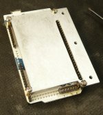
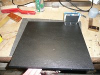
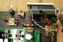
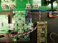
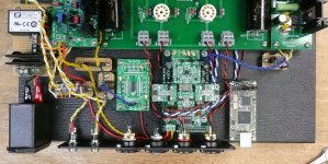
I've made the prototype board the same size as the planned internal dimensions of the final build.
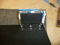
I have soldered header pins onto most of the Mega pins that aren't being used by the screen and made the bracket so they can be easily accessed.
I wont have much time in the next couple of weeks so it is going to be slow.
I have soldered header pins onto most of the Mega pins that aren't being used by the screen and made the bracket so they can be easily accessed.
I wont have much time in the next couple of weeks so it is going to be slow.
Attachments
Last edited:
Ideally your Power amps will have a 12v Trigger input already built in, if they don't, you will need to build some sort of trigger device that you would plug the amps into. I'll run through what I have done in the hope it helps.
The only reason my trigger is 12v is that when I started this audio diy odyssey I had an AV Receiver that had 12v trigger outputs so I used them to control the system as I built it up. The trigger can be whatever voltage (ideally low voltage DC) is convenient as long as you can get relays with coils (could be SSR) that match the trigger voltage. I would probably use 5v if I wasn't tied into the 12v at the beginning.
With my existing DAC when I turn the power on with the remote (the Arduino inside the DAC is always on) the first thing it does is turn the DAC section on, so an Arduino output switches on a relay that connects the DAC's transformers to the incoming AC. Then the Arduino sends a signal (5v) to a relay (coil) (still inside the DAC) that switches on the 12v output which is supplied by the 12v SMPS, this output is connected to my ASP crossover, the incoming 12v switches on a relay (12v coil obviously) that connects the AC power inside the crossover. Then the Arduino does the same thing for the amps. Obviously you want the amps to turn on last & turn off first so the routine is reversed at turn off. The DAC and Crossover can actually turn on at the same time.
If you don't have triggers inside the amps, you would just need a small box with power AC entries in and out, a relay or 2 and an incoming trigger connection that would feed the power for the relay coil.
I hope this is not too confusing, if you need anything else just ask, but bear in mind I'm a carpenter not an electronics guy.
That's really helpful, thank you. The amps I'm connecting to already have a 12 input trigger so I guess all I really have to do is to add a 12v output socket to the DAC for which I'll need a separate 12v supply. Your point about getting the amps to switch on last is a good thought though. I'm planning a tube output stage, so I'd much prefer the tubes to be powered up before triggering the amps to switch on. So, I guess the inclusion of a relay might be necessary.
I am using a soft start module from here: http://www.hypex.nl/docs/softstart_datasheet.pdf
This allows me to use a push-button on/off rather than mains switch but your arduino solution is much more elegant. I will have to check out the whole arduino thing as I can sense a stage 2 and 3 coming to this project!
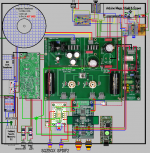
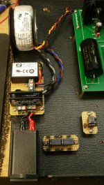
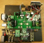
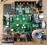
In the first instance I have decided to go with Version 5 & will move on to V5a once it is up & working.
V5 uses relays for the Source switching & the SPDIF/DSD switching. The Arduino & BIISE are isolated except for the I2C connection, V5a will have an isolator on the I2C. The Amanero will not be isloated in this version but will be in the V5a version.
Have made a start on the wiring but things will progress slowly due to time constants, my fancy soldering iron stopped working last night so this morning I dragged out my old iron which came directly from China, what a difference, can't wait for the new one to be fixed. Fortunately it is still under warranty It's a bit disappointing that the new Weller which cost 3 x the Chinese one stop after 11 months of light work & the Chinese clunker is still going.
V5 uses relays for the Source switching & the SPDIF/DSD switching. The Arduino & BIISE are isolated except for the I2C connection, V5a will have an isolator on the I2C. The Amanero will not be isloated in this version but will be in the V5a version.
Have made a start on the wiring but things will progress slowly due to time constants, my fancy soldering iron stopped working last night so this morning I dragged out my old iron which came directly from China, what a difference, can't wait for the new one to be fixed. Fortunately it is still under warranty
It's a bit disappointing that the new Weller which cost 3 x the Chinese one stop after 11 months of light work & the Chinese clunker is still going.Attachments
Last edited:
Just saw your version 5...looking good ;-)
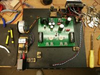
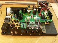
I noticed one thing missing on the wiring of the shunt to the tube-i-zator board. Shouldn't the return wire be connected to both sides of the audio out put stage (basically, the next pcb-hole to the left of where you have your return connection coming back from the shunt)?
I noticed one thing missing on the wiring of the shunt to the tube-i-zator board. Shouldn't the return wire be connected to both sides of the audio out put stage (basically, the next pcb-hole to the left of where you have your return connection coming back from the shunt)?
Just saw your version 5...looking good ;-)
I noticed one thing missing on the wiring of the shunt to the tube-i-zator board. Shouldn't the return wire be connected to both sides of the audio out put stage (basically, the next pcb-hole to the left of where you have your return connection coming back from the shunt)?
The wiring got the tick of approval from Oliver so I assume it is ok. http://www.diyaudio.com/forums/group-buys/156149-tube-i-zator-professional-pcb-74.html
The wiring got the tick of approval from Oliverhttp://www.diyaudio.com/forums/group-buys/156149-tube-i-zator-professional-pcb-74.html
Yeah, I saw that and I will be happy - and apologetic ;-) - if proved wrong but I do think it's worth another look. With the wiring as it is shown in your diagram, I can't see how the second valve receives any voltage. In other words, as I see it, we have to apply the return from the shunt to both points TB1 and TB2...not just one or the other. You currently have voltage going to TB2 which will supply the valve to the right of your diagram but I can't see how it would get to the other valve.
As I say, I'm only re-learning, having not built anything electronic in about 20 years, and I'm willing to learn and be told why I'm wrong...just trying to help.
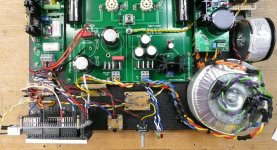
Getting there slowly, I have made all of the custom bits & pieces, but it may not be until next weekend before I get to put the rest of the bits on the board. I'm also building a bedside table & starting a Sub for the son's birthday which isn't far away, too many things to do so little time
Attachments
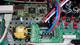
Nice work David!
As you may recall I use a Sidecar and added an OTTO II to switch between my Denon I2S and Amanero USB to I2S module inputs. I am using HiFiDuino/Corpius modified code. Setting I2S for the input selection pulls Sidecar HIGH.
The problem I had was the OTTO II would remain switched to input 2 when connected to the Arduino whether pin HIGH or LOW. When the Arduino UNO pins are set LOW, pin 7 had .009v DC. So does pin 6, etc. (Kind of surprised OTTO will switch with that low a voltage). To fix I made a relay board; now zero volts to S on OTTO when Arduino pin pulled LOW.
I added code to the input to switch OTTO HIGH for my Denon and LOW for my USB module. Worked great as long as I went clockwise with encoder or remote. If I went CCW, the OTTO relay would remain HIGH. This is what I did to fix it; add digitalWrite(OTTOPIN, LOW); to all other menu selections. Now I can go in either direction wih source selection and it works properly. You may have to do this too.
This code is located under:
void setAndPrintInput(byte value)
case 0:
digitalWrite(OTTOPIN, HIGH); //Switch OTTO HIGH to select the Denon. LOW for USB
lcd.print(no0);
break;
case 1:
digitalWrite(OTTOPIN, LOW);
lcd.print(no1);
break;
case 2:
digitalWrite(OTTOPIN, LOW);
lcd.print(no2);
break;
case 3:
digitalWrite(OTTOPIN, LOW);
lcd.print(no3);
break;
case 4:
digitalWrite(OTTOPIN, LOW);
lcd.print(no4);
break;
case 5:
digitalWrite(OTTOPIN, LOW);
lcd.print(no5);
break;
Attachments
Last edited:
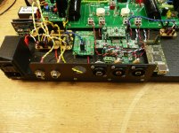
Getting closer all the time. The first TP/Arduino DAC that I build sort of evolved over time, where this one is straight to the end game, well almost. What are the chances of it all working first go Slim I'd imagine.
Slim I'd imagine.Attachments
I stumbled on these video's re soldering, I learn't a few things in the process, but if nothing else it's worth seeing what modern technology meant in 1980
PACE Worldwide's channel - YouTube
PACE Worldwide's channel - YouTube
- Status
- This old topic is closed. If you want to reopen this topic, contact a moderator using the "Report Post" button.
- Home
- Source & Line
- Digital Line Level
- DQ DAC 2, BIII SE, Tube-I-Zator, Arduino, Amanero Build