yes, no resistor at all. I think the bleeder is needed to give the choke a minimum supply or current draw. I think the chokes do not like the "no load" scenarios. But my DDDAC PSU is always drawing about 700mA (DDDAC mainboard with two DAC boards and WaveIO). So I think the DDDAC itself is my bleeder ;-).
Attachments
Hello,
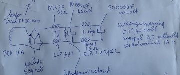
In the attachment you can see a drawing with Dutch language to explain how to do it to a diy friend.
With a choke input it is kind of mandatory to create a minimum current flow ALL the time by using the right resistor AFTER the choke.
Sure you can say that the shunt will be there to create enough current right from the start.
Because i am using a BIG choke with higher DCR i choose to use a bleeder because with no load at all the voltage across the cap will go up a lot. With the right bleeder it will drop to a value that will be safe for the caps with or without the circuit connected.
MAYBE you can raise the voltage a little bit by using other diodes. There is a big difference between 40 and 160 mH.
I started with a special LL2733 540mH 1,25A then changed it into LL2771 3000mH 1A when that one appeared on the market. Happily my diy DDDAC chassis was big enough to install the LL2771. I replaced the 500VA r core power transformer. The transformer in the drawing is around 15 euro. I am convinced that for choke input better invest in a bigger choke than a bigger transformer. The choke will create a nice steady charging current so the transformer and diodes will have an easy job.
Greetings, Eduard
Attachments
I’m not so sure how this behaves when going from Xlr (balanced) to rca (unbalanced).
Balanced to unbalanced - if two chassis are connected via Pin1 and both devices have a connection to house GND via power cables a large ground loop appears. In that case there may be a hum. In my device the Pin1 and PWR supply are grounded to the same point and then to the chassis via a 10ohm + 100nF + diode bridge. If hum appears at any time during use, I will tie Pin1 directly to the chassis. I'll try what happens when I find a balanced preamp. Currently, there is not the slightest hum at the RCA outputs.
The problem is that it is not possible to know in advance how Pin1 is connected in the following devices in the audio chain.
Last edited:
...if two chassis are connected via Pin1 and both devices have a connection to house GND via power cables a large ground loop appears. In that case there may be a hum...
Yes, there is a loop. However, this loop is not in the audio path, since the chassis/pin-1/shield is separate from the audio signals, which are on XLR pins 2 and 3 or on RCA tip and ring. All good.
The problem is that it is not possible to know in advance how Pin1 is connected in the following devices in the audio chain.
If the devices were made by a competent manufacturer/designer/builder, pin-1 will be connected to the chassis. Easy.
Yesterday I removed R2 from the standard PSU and replaced it with Lundahl 1694 choke ... Maybe I'll replace the cap after the choke (C3) with a bigger C the next days to see if there is another improvement.
If you go for a bigger C, I'd suggest to use a low ESR type. Or, even better, use several low ESR caps in parallel, which further reduces the total ESR. Going for a low ESR helps to attenuate the high-frequency noise before it enters the PSU regulator.
Last edited:
I’m not so sure how this behaves when going from Xlr (balanced) to rca (unbalanced).
You need to convert from XLR (DDDAC out) to RCA (amplifier input)? If your DDDAC has a transformer output, I'd suggest the following:
- Connect the DDDAC chassis to XLR pin-1.
- Connect the transformer secondaries to XLR pin-2 and pin-3.
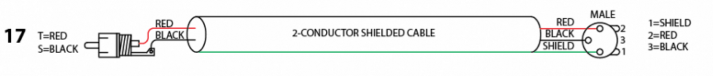
- Do not use the XLR/RCA conversion from your link, because it connects the audio GND to the chassis/PE (not good!).
- Instead, use the Rane #17 connection, but use the cable "backwards". This will connect the transformer secondaries (XLR pins 2 and 3) to the RCA "tip" and "ring" at the amplifier. The cable shield at pin-1 will be connected to the DDDAC chassis, but is separate from the audio signal.
This is how I connected my DDDAC to my USSA5 amplifier, which only has a single ended input.
Attachments

Last edited:
Not sure if this has already been posted, but the best piece I have read on earthing is one of the diyaudio articles by David Davenport, hopefully the link works:
Audio Component Grounding and Interconnection - diyAudio
Audio Component Grounding and Interconnection - diyAudio
Saw that some of the pictures was missing, this wayback version has them.
Audio Component Grounding and Interconnection - diyAudio
Audio Component Grounding and Interconnection - diyAudio
Thanks everyone for contributions on the grounding and pin 1 topic. good links to good articles.
As it is an important point for the DDDAC as well I let it go through, but would suggest we go back on topic as most is said.
Anyone who feels there need to be more discussion around it, just start a thread for it.
My Summary (these 4 points are what I do in praxis):
1. pin 1 always to chassis. make sure there is no audio signal flowing over pin 1
2. pin 1 only connects chassis with each other - signals hot cold (in SE hot and GND) are on pin 2 and 3
3. XLR out and using cinch SE at the other end: pin 1 is only connected to a shield at one side of the interlink 2 and 3 are signal GND and hot
4. in doubt, make a "lift switch" on all your equipment for connection audio gnd to chassis and see what gives best results
No need to respond to my summary (do not want to start over again - this is jut my experience")
may be I will write a short blog post on my blog site on how I ground my DDDAC and how it is build up internally....
As it is an important point for the DDDAC as well I let it go through, but would suggest we go back on topic as most is said.
Anyone who feels there need to be more discussion around it, just start a thread for it.
My Summary (these 4 points are what I do in praxis):
1. pin 1 always to chassis. make sure there is no audio signal flowing over pin 1
2. pin 1 only connects chassis with each other - signals hot cold (in SE hot and GND) are on pin 2 and 3
3. XLR out and using cinch SE at the other end: pin 1 is only connected to a shield at one side of the interlink 2 and 3 are signal GND and hot
4. in doubt, make a "lift switch" on all your equipment for connection audio gnd to chassis and see what gives best results
No need to respond to my summary (do not want to start over again - this is jut my experience
may be I will write a short blog post on my blog site on how I ground my DDDAC and how it is build up internally....
Last edited:
You need to convert from XLR (DDDAC out) to RCA (amplifier input)? If your DDDAC has a transformer output, I'd suggest the following:
This is how I connected my DDDAC to my USSA5 amplifier, which only has a single ended input.
As far as I understand the instructions for the DDAC1794 outputs, this connection is possible when there is a transformer at the output. When there are capacitors at the output (my case) then this connection is not possible.
Grounding the shield on the source side (where the impedance is low) is OK because it certainly solves ground loop and other problems. That's why you have to make balanced interconnect cables yourself and mark the grounded side of a shield.
Attachments
Last edited:
Newly posted Ultra Capacitor blog
Inspired by the many reports on the audiophile improvements when using UltraCaps (or super capacitors) in Audio applications, I decided it was time to start looking into this subject myself. For starters I wanted do some tests with it on my own DDDAC. Of course I am also interested in the technical aspects and possible use for future projects. But as always, get some facts first and listen to some music ....
read more here ! My UltraCap experiments - DDDAC
Attachments
So Super capacitors instead of battery's ...
What are you using ?Works great !
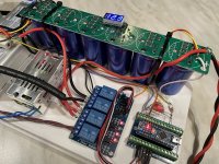
Stock dddac psu, no problem at all. Just remember to not connect load before power up the first time after the supercaps is installed, (if your psu deliver around 1A, as mine).If you have a bigger psu, 2-3A, you have enough juice to power up with load connected.
I was afraid that I have to disconnect the load if dac had been powered off for a few days or so, but so far so good. It takes only a few sec, and everything lights up on the Uccapacitor boards from Ian. Very pleased for time beeing.
I was afraid that I have to disconnect the load if dac had been powered off for a few days or so, but so far so good. It takes only a few sec, and everything lights up on the Uccapacitor boards from Ian. Very pleased for time beeing.
Attachments
Funny, this is exactly the topic i am struggeling with at the moment.received fifopi yesterday toghether with a 3.3v conditioner. Unfortunately i have not informed myself about startup charging currents. I connected the conditioner behind a 3.3v regulator board which is itself connected to dddac psu. Fifopi was connected to the conditioner. In this setup dddac 1A fuse blew about 3 times. I measured about 3 ampere at the fuse.i then removed the conditioner and everything was fine. This morning i read the manual and found the hint that the psu needs at minimun 1.5A for the first load of the super caps. If no such psu is available (like in my case) the load needs to be disconnected in the beginning (first load) So I connected the conditioner again but without load. In this setup the conditioner ran about 1 minute (the two LED were on in this time - OK). After about one minute it seemed that the conditioner turned into another state (tried to turn on other LEDs!?) and fuse blewed again. Did I kill the conditioner by connecting it with load in the beginning?
Fifopi ist great by the way. Better than waveio even without conditioner. I'm wondering if it is worth to further try to get the conditioner running!?! Cannot imagine to get further improvements, but this was also the case in the past and then I was surprised when there was another improvement.
Fifopi ist great by the way. Better than waveio even without conditioner. I'm wondering if it is worth to further try to get the conditioner running!?! Cannot imagine to get further improvements, but this was also the case in the past and then I was surprised when there was another improvement.
I had the same problem with a 5V Unconditioner that I was using to meet my DAC's 5V requirements. Just at switch over from charging to charged, it seems that the Unconditioner very briefly draws quite a few amps from the source supply. I did measure the spike using a recording meter, but I don't seem to have recorded the value in my notes. It was sufficient to blow the 3Amp quick blow fuse that was installed in the Salas L-Adapter used as the source. Since this L-Adapter is built to deliver many more amps, I upped the fuse to an 8Amp slow blow as specified in the original L-Adapter design. Not had any problem since then.
- Home
- Source & Line
- Digital Line Level
- A NOS 192/24 DAC with the PCM1794 (and WaveIO USB input)