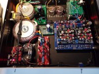
Connected the dddac directly direct to the amp camp seems to give better lows but less detail. The input impedance of the amp is to low for the Cinemag transformers so that could be the problem
I am about to move to another house and my other amp (Sugden A21) is already packed. I think that combination will be better, the input impedance is 47k. To be continued.
Or just upgrade to Cinemag 600 trafos, lol.
I am about to move to another house and my other amp (Sugden A21) is already packed. I think that combination will be better, the input impedance is 47k. To be continued.
Or just upgrade to Cinemag 600 trafos, lol.
Attachments
3kes:
I see now that your buffer is after the Cinemags and that your Cinemags are connected directly to the DDDAC outputs. Nice build!
To get significantly more bass and improved SQ throughout the entire audible frequency range you either need to add at least 3 more DAC boards or put a balanced buffer(with power supply) between the DDDAC outputs and the Cinemags.
3kes:
I see now that your buffer is after the Cinemags and that your Cinemags are connected directly to the DDDAC outputs. Nice build!
To get significantly more bass and improved SQ throughout the entire audible frequency range you either need to add at least 3 more DAC boards or put a balanced buffer(with power supply) between the DDDAC outputs and the Cinemags.
Do you mean a single board dddac with Cinemangs isn't the best combination?
And how about just remove the cinemags and connect the dac directly to the B1 Buffer? There is a big Mundorf capacitor on the line in the B1.
3kes:
I see now that your buffer is after the Cinemags and that your Cinemags are connected directly to the DDDAC outputs. Nice build!
To get significantly more bass and improved SQ throughout the entire audible frequency range you either need to add at least 3 more DAC boards or put a balanced buffer(with power supply) between the DDDAC outputs and the Cinemags.
Do you mean that a single board dddac with Cinemangs isn't the best combination?
And how about just remove the cinemags and connect the dac directly to the B1 Buffer? There is a big Mundorf capacitor on the line in the B1.
3kes:
I see now that your buffer is after the Cinemags and that your Cinemags are connected directly to the DDDAC outputs. Nice build!
To get significantly more bass and improved SQ throughout the entire audible frequency range you either need to add at least 3 more DAC boards or put a balanced buffer(with power supply) between the DDDAC outputs and the Cinemags.
I've read you're threat about the buffer. Are those buffer pcb's still available? Three extra DAC boards are a pretty expensive upgrade.
I agree that more DAC boards might be one way to go. However, if you want / need to use a buffer anyway, I'd suggest to use a buffer with balanced inputs that are happy with a bit of DC (about 2.6 V) coming from the DDDAC outputs. Then you could simply skip the transformers. I know that others went this way, and I am sure someone will have suggestions for suitable buffers.
Hi,
Back in late 2014, early 2015 I built a somewhat modified single board DDDac which included 8V Tentlab shunt regulators. Unfortunately, at the time, I had to put the project on hold for family reasons prior to completion. Over the last couple of months, I have resurrected the project and now have a working DDDac.
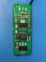
Recently, I became aware that some source material played through the DDDac sounded somewhat distorted, so decided to investigate. Eventually, I measured the output of the 8V Tentlab shunts and discovered that they were only outputting 4V6. Seems a bit strange. However, looking back through this thread, it seems other who bought shunts around the same time have had the same problem (see posts #3800). Unfortunately, I can’t quite determine for sure how the problem was resolved. It looks like the current limit on the shunt is incorrectly set, and that I need to add a resistor. Not sure what the value is, or exactly where to add it.
Can anyone help?
Also, how much analog side current does a single PCM1794 DAC chip need on each DDDac board?
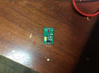
Attached is a image of the component side of one of my 8V Tentlab shunts.
Thanks. —nick
Back in late 2014, early 2015 I built a somewhat modified single board DDDac which included 8V Tentlab shunt regulators. Unfortunately, at the time, I had to put the project on hold for family reasons prior to completion. Over the last couple of months, I have resurrected the project and now have a working DDDac.
Recently, I became aware that some source material played through the DDDac sounded somewhat distorted, so decided to investigate. Eventually, I measured the output of the 8V Tentlab shunts and discovered that they were only outputting 4V6. Seems a bit strange. However, looking back through this thread, it seems other who bought shunts around the same time have had the same problem (see posts #3800). Unfortunately, I can’t quite determine for sure how the problem was resolved. It looks like the current limit on the shunt is incorrectly set, and that I need to add a resistor. Not sure what the value is, or exactly where to add it.
Can anyone help?
Also, how much analog side current does a single PCM1794 DAC chip need on each DDDac board?
Attached is a image of the component side of one of my 8V Tentlab shunts.
Thanks. —nick
Attachments
Hi,
Back in late 2014, early 2015 I built a somewhat modified single board DDDac which included 8V Tentlab shunt regulators. Unfortunately, at the time, I had to put the project on hold for family reasons prior to completion. Over the last couple of months, I have resurrected the project and now have a working DDDac.
Recently, I became aware that some source material played through the DDDac sounded somewhat distorted, so decided to investigate. Eventually, I measured the output of the 8V Tentlab shunts and discovered that they were only outputting 4V6. Seems a bit strange. However, looking back through this thread, it seems other who bought shunts around the same time have had the same problem (see posts #3800). Unfortunately, I can’t quite determine for sure how the problem was resolved. It looks like the current limit on the shunt is incorrectly set, and that I need to add a resistor. Not sure what the value is, or exactly where to add it.
Can anyone help?
Also, how much analog side current does a single PCM1794 DAC chip need on each DDDac board?
Attached is a image of the component side of one of my 8V Tentlab shunts.
Thanks. —nick
Hi Nick, I cannot comment the shunt thing, but on the website from Tentlabs you have the formula for the resistor. The DAC takes roughly following current: Analog side of the chip (the 8 Volts) takes about 35mA-40mA and the digital side consumes ~ 15mA-20mA - that is for each "half dac board"
hope that helps.
General comment for everyone: The quickest way to see if your Dac is biased well is to measure the DC voltage (no music) between Common and POS and Common and NEG. So you have 4 voltages, they need to be close to each other within max 25mV or so and in absolute value round 2.8Volt (the last value is not sooo critical, can be 2.72 or 2,87 for example, but the values should be in that range and more important close to each other
Hi Nick, I cannot comment the shunt thing, but on the website from Tentlabs you have the formula for the resistor. The DAC takes roughly following current: Analog side of the chip (the 8 Volts) takes about 35mA-40mA and the digital side consumes ~ 15mA-20mA - that is for each "half dac board"
hope that helps.
That helps a bit though I can't find current limiting resistor configuration mentioned on the Tentlabs website. There is a discussion about voltage droppers in case of excess input voltage, but I'm supplying them with just under 12V.
For sure, my regulators will not supply more than 35mA at 8V. By the time they are sourcing 37mA, they are already below 8V.
If your regulators cannot supply more than 35mA you have the wrong ones - did you try emailing Guido Tent and ask for a possible solution? May be he can advise you which resistors to change so the current will be approximately 70-80mA - As you are using them with 12 volt max, Dissipation should not be a problem than.
Worth a try before buying new ones ?
I am selling my Audio Precision PCI-APIB APIB PCI Interface Card
Audio Precision PCI-APIB APIB PCI Interface Card Module 2322 2722 series | eBay
just in case any one needs this...
Audio Precision PCI-APIB APIB PCI Interface Card Module 2322 2722 series | eBay
just in case any one needs this...
Doede: What type/manufacturer of resistor 6k was delivered in the first versions of DAC board kit from you? It was black in color.
Dale 6k 1% Digikey CMF6.04KQFCT-ND
CMF506K0400FHEB Vishay Dale | Widerstande | DigiKey
Thanks to everyone and to Guido for very quick email response.
I have reconfigured the current limiting resistors on the Tentlab shut regulators to supply between 70mA and 80mA at 8V and now they work perfectly. The DDDac also now work well with the test track that previously cause significant distortion and led me to check for problems.
I have reconfigured the current limiting resistors on the Tentlab shut regulators to supply between 70mA and 80mA at 8V and now they work perfectly. The DDDac also now work well with the test track that previously cause significant distortion and led me to check for problems.
Thanks to everyone and to Guido for very quick email response.
I have reconfigured the current limiting resistors on the Tentlab shut regulators to supply between 70mA and 80mA at 8V and now they work perfectly. The DDDac also now work well with the test track that previously cause significant distortion and led me to check for problems.
Thanks for the feedback and happy that all works fine now !!
")
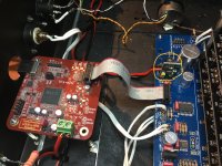
updating my power supply
Hello,
After a few months of absence i decided to return to share some thoughts.
Right now i am in the process of changing my choke input power supply into anothyer choke input power supply because my favourite choke brand did introduce a new choke on the market.
It is rated 3000mH at 1A my old input choke was 1000mH at 0,7A. Probably 1A was a bit to much to use it in choke input configuration. I did make a test on my kitchen table with the chokes i had in series to come close to the future 3000 mH. I measured ac voltyage drop across each choke. 544mH and 1000mH do have the same dcr but the bigger has of course a smaller airgap to create more mH. AC voltage drop across 544mH is around 5,2 volts, across the 1000mH there is 7,2 both with 1 A current. 7,2 volt should be higher because 544 times 1,8 is 1000mH. What it makes lower is saturation of the core.
When turning up the current to 1,2 A . The drop of 5,2 goes up to 7,2 volts but the drop across the 1000mH goes down to 2,7 volts. It isnt acting as a choke anymore just a 3,4 ohm resistor.
In the past i told i read about a certain amount of current that could be add if the ac voltage is lower than the one used to measure the mH at the nominal current. Now working with a transformer with a higher ac output because of there will be a big voltage drop when using 3000mH it seems better to not use 1000mH but just switch to the 544mH 1,25 A ( that is if i cannot get the right output voltage with my new transformer.
Will keep you informed.
Doede told me the results couild be very nice.
Greetings, Eduard
- Home
- Source & Line
- Digital Line Level
- A NOS 192/24 DAC with the PCM1794 (and WaveIO USB input)