r core voltage
Hello,
I did do some testing with the R core 300va 2*15 volts today. When using the LL2733 as common mode input choke ( 400mH total; indictance and 3.4 ohm total serie resistance) the dc voltage will be to low. I did use a bleeder to simulate one motherboard , 4 dac boards with shunts and a bleeder that will guarantee choke input when something goes wrong. So about 1,1A I end up with about 8.2 volts at the first cap so not even using the second choke. Which will take about 2 volts more.
So will probably need to get a 2*21 volts. Can also change the position of the two chokes so use the LL1694 as the input choke with its lower serie restance 1.8 instead of 3.4 voltage loss will be much smaller because the input choke has higher loss because it is dealing with ac too because it is in front of the first cap.
After making a screen for all my chokes and transformers and potting them i will put the 300va 2*15 for sale.
Sincere greetings, edward
OK Guys, here is some answer ........
Very intresting.
@Doede, I have a few questions that are nagging me. Just to be clear I'm not question your choices to be critical, but merely to gain a better understanding of some of the design choices . Looking at the PCM1794 datasheet I see the "typical" application example shows 10uf's at VCC, can you share with us how you came to using 47uf's? Before I expected this came about through trial and error, but I’m starting to doubt my assumption now that your testing the Vcom capacitor. Also what made you chose 4x 47uf's in parallel after Vb? Was this due to size/height restriction and simplicity of assembly, or did you try different values and found this the best sounding option?
Hello,
I did do some testing with the R core 300va 2*15 ...
Sorry to hear you have to revisit your PS design.
Very intresting.
@Doede, I have a few questions that are nagging me. Just to be clear I'm not question your choices to be critical, but merely to gain a better understanding of some of the design choices . Looking at the PCM1794 datasheet I see the "typical" application example shows 10uf's at VCC, can you share with us how you came to using 47uf's? Before I expected this came about through trial and error, but I’m starting to doubt my assumption now that your testing the Vcom capacitor. Also what made you chose 4x 47uf's in parallel after Vb? Was this due to size/height restriction and simplicity of assembly, or did you try different values and found this the best sounding option?
Hi Stijn,
Neither is 100% the case... When I made my prototypes, I was not yet in the possession of the Audio Precision analyzer … So I used les advanced equipment, some trial and error and of course my ears. On the Vcom capacitors, I noticed that there was a decoupling effect with a low pass filter on it. With 47uF the DAC soft-started up in like a second or so I took this for a good compromise between low pass filter for the audio band and practical choice for the capacitor value I did not do extensive listening test on these parts though. After the power supply was choice for keeping the return path as local as possible. Again, 47uF is a good compromise between low pass filter value and space on the PCB. I do not believe these values to be overly critical. Quality of the part yes, which is how I came to the Nichicons (value / SQ Performance)
On a philosophical note, basically the choices are endless.... at some point you just pick what is a good compromise between performance and practicality (Size and Budget belongs to this among others)
fourth option
I may have a better option, with much better reproducibility... No sorting necessary and performance is a bit better than any among those three. I want to run some breadboard tests tho. Again, the voltage and current is so low that things are a bit funky down there.
It's a three-legged thingie, though, so not entirely sure how it fits the application. Reason for further tweaking / thinking.
aR
cheers rax thats great
i suppose we would like to be able to vary the current a little, so option three would likely suit.
difficulty finding 1N5288 anyway
could you point us towards a schematic, bom please
thx again rax
I may have a better option, with much better reproducibility... No sorting necessary and performance is a bit better than any among those three. I want to run some breadboard tests tho. Again, the voltage and current is so low that things are a bit funky down there.
It's a three-legged thingie, though, so not entirely sure how it fits the application. Reason for further tweaking / thinking.
aR
How many decks etc?
You running balanced into amps?
Forgot myself bit excited
1 deck
Im not running balanced to amps but bal out should be ok and still benefit
Using a 2.2 cap for unbalanced still required
I may have a better option, with much better reproducibility... No sorting necessary and performance is a bit better than any among those three. I want to run some breadboard tests tho. Again, the voltage and current is so low that things are a bit funky down there.
It's a three-legged thingie, though, so not entirely sure how it fits the application. Reason for further tweaking / thinking.
aR
Super stuff
Looking forward to it
Thnx
Sounds great. I'm certainly happy with a more funky solution if the results are worthwhile. For those of us not using the electrolytics around the DAC chip, there's a fair bit of room to play withI may have a better option, with much better reproducibility... No sorting necessary and performance is a bit better than any among those three. I want to run some breadboard tests tho. Again, the voltage and current is so low that things are a bit funky down there.
It's a three-legged thingie, though, so not entirely sure how it fits the application. Reason for further tweaking / thinking.
aR

Also looking forward to Doede's findings on the vcom caps. It would be nice if a smaller value than 47uf would work, as it would help with availability. I wonder if an OSCON would work well here?
I put some more time into the DDDAC last night. After I’d invested in a proper desoldering station, it was light work getting the remaining Muse caps of my boards.
Aside from this forum, a friend Cees Pel, has also had a go at trying different cap configurations on the DDDAC, which he shared with me. I took a great deal of inspiration from him in coming up with the following scheme and also from the scheme’s Stefan has posted in the forum. So they get the credit for some of most of these idea's. What Cees had done differently compared to Stefan was, use Oscon’s at the analogue side of the PCM1794’s and higher value Silmic’s on the board it self. I thought these to be good idea’s
I replaced:
· C1-C4/C7-C10 with a 200uf 20V Silmic II each side with a little filtering cap (Wima, 0.68uf 63v) across them.
· C5/C11 with a 100uf 25V Silmic II each side with a little filtering cap across them.
· All the 47uf caps at Vdd/Vcc/Vcom’s with Oscon’s 47uf 20V
· C13/C15 both sides with Oscon 100uf 20V
· Lastly 22nF 63V Polysterine caps for HF filtering at the output.
I don’t want to sound like every change I make is “the best thing since sliced bread”. But the way it stands now, the soundstage and separation has improved in a big way, everything has become cleaner and more accurate. Tonality has improved, highs have cleaned up, I can hear “around” things like cymbals..
Changing to this caps scheme must be the single biggest improvement I made to my DAC so far...
Thanks again guys for your inspiration and Doede for giving us such a great dac design to tweak
Last edited:
....
I wonder if an OSCON would work well here?
It does, very well.
Hi Stijn,
Neither is 100% the case...
Thanks, nice that your recent measurements confirmed your initial impressions.
The fact that you designed the boards to allow for these endless combination is what is making it such a great DIY DAC.
....
Would you please let me know where I could get those Oscon?
Chanh, I got all of them from Mouser.com, they also have a good selection of small size Silmic's and Wima's.
You can also buy OSCON from panasonic now. They are the SEP series and they seem to be quite well stocked (at least here in the UK they are)Hi stijn001,
Thanks for sharing!
Would you please let me know where I could get those Oscon?
Thanks stijn001!Chanh, I got all of them from Mouser.com, they also have a good selection of small size Silmic's and Wima's.
I wonder with this caps arrangement, in especially the Oscon at analog side, would sound like it gives extra resolutions/details at top ends but with a very thin midrange? I ask because I have been experimented many DACs before this one, where I stopped and found love with this particular DAC chip design from Doede. Hence so much efforts plus funding were investing til date.
Based on my last 12months with many gtg(s) of various DACs, I found those extra details/resolutions at top ends might gave a first impression of clarity, separation, and resolution..., however, will a prolong listening period be fatigue? A realistic example is where I found the ESS Sabre 9018 has failed me. The sound from Sabre was too clinical/digital for my ears but this is entirely personal taste and system's synergy. Here not to say Sabre is negative!
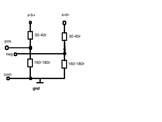
Im having great results with this iv
is someone up for trying it?
Just to update seems best to keep the sum of the iv resistors on each differential leg under 200r
Starts to distort above 200r
I'd like to try a value of 40r and 150r but don't have a suitable 40r
I might get a variety of suitable r's to test
Neglected to say this is for one deck
Last edited:
Chanh, I had the same concern. But I must say I’m pleasantly surprised. The added 100uf and 200uf Silmic caps might give it more body and balance out the precision and clear high-end of the 47uf Oscon’s. Also everything depends on the rest of the system, music style/recording, personal preference.
All I can say is I love what I’m hearing and I’m going to stick with them for a while.
Also I’m trying to stay as objective as possible. Not to think it “should” sound like this or that due to using this or the other. But rather to let the quality of the experience decide.
btw, I used to own a Sabre 9018 based dac as well. I know what you mean with it sounding digital.
Last edited:
- Home
- Source & Line
- Digital Line Level
- A NOS 192/24 DAC with the PCM1794 (and WaveIO USB input)