Judging by the nrs you'are quoting, is this shop your talking about?
Résultats de recherche pour : 'Transformateur R-CORE à fixation sur châssis 300VA'
Sure Stijn, that is the one i think i did post the link before or maybe i did in a private message to Chanh
Second document from the top, DDDAC 1794S
DDDAC 1794 NOS DAC - Non Oversampling DAC with PCM1794 - no digital filter - modular design DIY DAC for high resolution audio 192/24 192kHz 24bit
Thanks for the link. So it only applies to the USB /SPDIF version or if using more than 4 boards?
with 4 boards which I've got it seems to offer an improvement too
David
Is that this product?If that is the case, this isolator will be interesting? Isolate your Raspberry PI
It costs only US$125.
Please see attachment below w.r.t Designer's response to my online query.
Isolation - G2 labs
It's weird... they hardly mention that it's a I2S reclocker, but in theory, that part of it is much more significant than the fact it's an isolator, which is pretty easy to achieve.
Buying one of those certainly looks a lot easier than making an Acko board, but I don't know enough about this to judge whether this implementation is likely to perform as good
Is that this product?
Isolation - G2 labs
It's weird... they hardly mention that it's a I2S reclocker, but in theory, that part of it is much more significant than the fact it's an isolator, which is pretty easy to achieve.
Buying one of those certainly looks a lot easier than making an Acko board, but I don't know enough about this to judge whether this implementation is likely to perform as good
I just ordered the Isolation. Sounds like just what the RPi needed, reclocking and isolation for the I2S out. I have been watching the Botic discussion, and there is still doubt in my mind as to whether it will even work for the DDDAC, although I will continue to follow for possible use in a future DAC. I already have secured the RPi and a BBB.
That being said, the new USB->I2S board from Sonore looks pretty good too. ?better than Wave I/O?
Hi Bones13,I just ordered the Isolation. Sounds like just what the RPi needed, reclocking and isolation for the I2S out. I have been watching the Botic discussion, and there is still doubt in my mind as to whether it will even work for the DDDAC, although I will continue to follow for possible use in a future DAC. I already have secured the RPi and a BBB.
That being said, the new USB->I2S board from Sonore looks pretty good too. ?better than Wave I/O?
Please keep us posted with your findings for this isolator?
I too have BBB Rev C and RPi, and await for Botic Cape but doubtful! Therefore, I am keen on this isolator but gutless taking the punch!
")
Best,
Chanh
Of course it says available on the website, but right after they accepted the PP money, they sent an email saying it is "backordered". On this type of company, though, they could be soldering stuff up once it is ordered. Shipping is "10-30 days", so it will be awhile.
My current DAC board only takes SPDIF input, so I won't be able to try it out until I get a DDDAC up and running.
Now, if I just start populating my boards... And order an enclosure.
My current DAC board only takes SPDIF input, so I won't be able to try it out until I get a DDDAC up and running.
Now, if I just start populating my boards... And order an enclosure.
was wondering if there was a better way than using a resistor for the bias
when i came across this:
"However, it employs a cascode connected depletion mode MOSFET constant current source (CCS)"
here
K & K Audio - Lundahl Transformers, audio DIY kits and more
does anyone know how to implement an external CCS
when i came across this:
"However, it employs a cascode connected depletion mode MOSFET constant current source (CCS)"
here
K & K Audio - Lundahl Transformers, audio DIY kits and more
does anyone know how to implement an external CCS
simpler is (almost) always better. Passive I/V, if outputting enough for the rest of your chain, is hard to beat, and active amplification should only be used if necessary. Did you need this additional gain? KK's DAC also uses passive I/V conversion, but an additional tube stage. The CCS is probably there to feed this additional stage and provide a typically excellent PSRR.
Last edited:
It's $35 posted for the board, then the digikey order was something like $75 and a maybe $10 from Potato Semiconductors too.
I still need to work out the best way to get from the U.FL connectors onto the DDDAC mainboard, so I guess a few $ more still to come
Hi James,
I just read your post and I don't know if you have been solved the U.FL cable connection to the DAC.
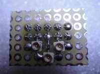
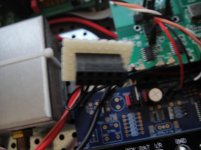
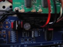
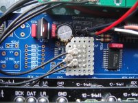
Anyway, I solve the problem with a small (very DIYer) pcb, 3 U.FL connectors and Molex female connector.
The molex connector can be used for both the DAC motherboards.
If you use the old type the connector will go straight in the input connector.
I have the new board and I use both the RPI+S03 and the Waveio.
I leave the input connector for the Waveio. For the S03 connection I made a small modification: I remove the IC WM8804 (is part of the S-PDIF input that I don't use), I solded the 3 100ohm resistor on the back side of the board and I use the 3 holes for a small molex connector.
Attached are some pictures about... I hope this can help you
Regards,
Enrico
Attachments
Thanks Enrico, that's very helpful.Hi James,
I just read your post and I don't know if you have been solved the U.FL cable connection to the DAC.
Anyway, I solve the problem with a small (very DIYer) pcb, 3 U.FL connectors and Molex female connector.
The molex connector can be used for both the DAC motherboards.
If you use the old type the connector will go straight in the input connector.
I have the new board and I use both the RPI+S03 and the Waveio.
I leave the input connector for the Waveio. For the S03 connection I made a small modification: I remove the IC WM8804 (is part of the S-PDIF input that I don't use), I solded the 3 100ohm resistor on the back side of the board and I use the 3 holes for a small molex connector.
Attached are some pictures about... I hope this can help you
Regards,
Enrico
I hadn't solved this little issue yet as I haven't found the time for the tiny SMD soldering on the S03.
This looks like a nice method, I'll give it a go.
cheers,
James
simpler is (almost) always better. Passive I/V, if outputting enough for the rest of your chain, is hard to beat, and active amplification should only be used if necessary. Did you need this additional gain? KK's DAC also uses passive I/V conversion, but an additional tube stage. The CCS is probably there to feed this additional stage and provide a typically excellent PSRR.
in my haste i quoted the wrong bit,
"The designer, Dave Davenport of Raleigh Audio , has added another PCM1794 DAC chip so that each dac is operated in "mono mode", meaning that both DACs in each chip are serving only one channel's data stream in a differential configuration, resulting in greater linearity and higher current output. Each of these DAC chips is receiving reference current from a new reference current source that we have developed, which is responsible for a dramatic improvement in sound quality"
what i meant to ask was if running a CCS to pin 20 of PCM1794 can be done or if a ccs can be used or in what way the RAKK DAC might be doing it?
Thanks Enrico, that's very helpful.
I hadn't solved this little issue yet as I haven't found the time for the tiny SMD soldering on the S03.
This looks like a nice method, I'll give it a go.
cheers,
James
You are welcome...
Last edited:
in my haste i quoted the wrong bit,
"The designer, Dave Davenport of Raleigh Audio , has added another PCM1794 DAC chip so that each dac is operated in "mono mode", meaning that both DACs in each chip are serving only one channel's data stream in a differential configuration, resulting in greater linearity and higher current output. Each of these DAC chips is receiving reference current from a new reference current source that we have developed, which is responsible for a dramatic improvement in sound quality"
what i meant to ask was if running a CCS to pin 20 of PCM1794 can be done or if a ccs can be used or in what way the RAKK DAC might be doing it?
Interesting... Coincidentally, I was looking at K&K a while back when I was thinking of swapping the current source for the cathode bias in my tube amp from a simple resistor to a Constant Current Source (CCS). They do a small 2 pin adjustable CCS module in their accessories section here - K & K Audio - Lundahl Transformers, audio DIY kits and more
An externally hosted image should be here but it was not working when we last tested it.
Although I suspect we wouldn't need anything like the wattage rating of these CCS that are made with valve amps in mind and also, they're more complex than needed by virtue of being adjustable. It should be fairly easy to make one yourself with only a small handful of cheap components.
Sounds like it might be worth a try.
Finally my Shunts arrived, they look so adorable.
The solder-iron has been running hot since yesterday! There were lots of work and patience in desoldering every single board here. With yours inspiration, I have finally coming down to my last few boards.
Today I will be populating the boards. The idea is to have all resisters and caps replaced by AudioNote 0.5W reisisters and Elna Silmic 2 for analog and Oscon SVP for digital. I could not get Oscon SEP like Supersurfer here in Australia. There are some Oscon SC coming also but am not sure which is the better, SVP or SC (new old stock)? Your experience inputs are appreciated!
@Stefan & James - I see you two have bypassed all stock inductors, however, James went further bypassed the R2 as well. So my lazy question is has James experimenting both with and without R2 and found without R2 yield better SQ?
An externally hosted image should be here but it was not working when we last tested it.
An externally hosted image should be here but it was not working when we last tested it.
An externally hosted image should be here but it was not working when we last tested it.
An externally hosted image should be here but it was not working when we last tested it.
An externally hosted image should be here but it was not working when we last tested it.
in my haste i quoted the wrong bit,
"The designer, Dave Davenport of Raleigh Audio , has added another PCM1794 DAC chip so that each dac is operated in "mono mode", meaning that both DACs in each chip are serving only one channel's data stream in a differential configuration, resulting in greater linearity and higher current output. Each of these DAC chips is receiving reference current from a new reference current source that we have developed, which is responsible for a dramatic improvement in sound quality"
what i meant to ask was if running a CCS to pin 20 of PCM1794 can be done or if a ccs can be used or in what way the RAKK DAC might be doing it?
I don't know the answer to that specific question. But, depending on the current requirements, there are many other types of CCS configurations that will do a better job at lower currents (the cascode depletion mode MOSFETs K&K uses are ideal for high voltage / medium to high - as far as CCSs go - current). I can direct you to other configurations and help some with which one may fit better etc. And yes, you can put them together yourself w/out kits from some source.
I don't know the answer to that specific question. But, depending on the current requirements, there are many other types of CCS configurations that will do a better job at lower currents (the cascode depletion mode MOSFETs K&K uses are ideal for high voltage / medium to high - as far as CCSs go - current). I can direct you to other configurations and help some with which one may fit better etc. And yes, you can put them together yourself w/out kits from some source.
yes a little direction would be fantastic
i was hoping someone had tried something like this already
the voltage is 2.4v
i haven't measured the current, is there a specific or a best way to measure it?
if we can get a list of parts ill get on it straight away!
thx rax
Wow Chan, that's some serious work right there@Stefan & James - I see you two have bypassed all stock inductors, however, James went further bypassed the R2 as well. So my lazy question is has James experimenting both with and without R2 and found without R2 yield better SQ?
That will keep you busy for a good few hours yet...
The simple (and not so helpful) answer is, I don't remember the motivation for doing this, sorry
.... To answer your question directly, it wasn't done as a result of me doing my own comparative listening tests. I don't believe that my ears are good enough to record very subtle differences, especially if there is any significant time gap inbetween. I have a picture of one of Stefan's setups with these resistors bridged, but with the chokes still in place. I guess I may have taken the lead from that.I see that on the latest board schematic for Doede, they are listed as 10ohm.
That'd be very interesting to try and real nice if it's possible to easily put together a small 2 pin setup that can simply go in place of the bias resistor. If this resistor is currently 6kohm @ 8v (and I'm not certain if it is 8v here) then that makes it a 1.33ma current right?I don't know the answer to that specific question. But, depending on the current requirements, there are many other types of CCS configurations that will do a better job at lower currents (the cascode depletion mode MOSFETs K&K uses are ideal for high voltage / medium to high - as far as CCSs go - current). I can direct you to other configurations and help some with which one may fit better etc. And yes, you can put them together yourself w/out kits from some source.
Here's what Doede wrote about calculating the bias:yes a little direction would be fantastic
i was hoping someone had tried something like this already
the voltage is 2.4v
i haven't measured the current, is there a specific or a best way to measure it?
if we can get a list of parts ill get on it straight away!
thx rax
the rest of the investigation are here: - DDDAC 1794 NOS DAC - Non Oversampling DAC with PCM1794 - no digital filter - modular design DIY DAC for high resolution audio 192/24 192kHz 24bitDoede said:Finding the optimum Bias and Output Voltage
Indeed a very tricky business... I quickly found out, that there is no real correlation between the reference resistor value (at pin 20) and the output current. The output current at zero signal level is of course resulting in the output DC voltage, which again is important for the maximum output signal which should not clip against ground and the positive supply voltage. One thing was clear, the higher the analog supply voltage, the more headroom for the DAC internal current sources. The datasheet tells us, that the maximum Vcc (analog supply) is 6,5 Volt. Oh really? This is just a current source, hard to believe after my experience with the TDA1543, that this is really the maximum. This is the most easy test... Play music, connect the VCC to a LAB power supply and slowly increase the supply voltage. Measure the supply current and wait till it SMOKES
I learned, that the following was the optimal situation
Vcc 8 Volt
R ref 6,1KOhm
R Load 270 Ohm, resulting in a Bias of 2,72 Volt
Current Output at zero signal ~ 10mA allowing headroom for full scale current (6,3mA)
Full scale voltage swings between 1,0V and 4,4V (4,5V is max before clipping)
Full scale voltage RMS therefore 1,2V RMS
d2 and d3 below 0,2%, which is very good for passive I/V
Here's what Doede wrote about calculating the bias:
the rest of the investigation are here: - DDDAC 1794 NOS DAC - Non Oversampling DAC with PCM1794 - no digital filter - modular design DIY DAC for high resolution audio 192/24 192kHz 24bit
ok ill look into it,
mines reading 2.4v
i was experimenting with various resistors the one thats in it now is likely not exactly 6k
- Home
- Source & Line
- Digital Line Level
- A NOS 192/24 DAC with the PCM1794 (and WaveIO USB input)