I asked this question months ago and did not get an answer from Doede.
I wonder if it has something to do with the SPDIF input? But have no idea.
Maybe with two asking we will be told?
sorry I must have mist this... I do get quite some mail and questions, so sometimes....

any way, it is all described in detail in the updated pages on my web site
Spdif page blue board
please have a read here and feel free to ask again if not clear
one other thing on blue or red..... the older red boards drive max 4 dac boards.... the blue board, thanks to improved buffering, so far 11 boards. limit not know yet
if you do not need spdif or more than 4 dac boards, the red one is fine.
James don't worry on sales aspects as you all know this is just hobby for me. what ever is sold, pays for stuff like prototypes and expensive equipment like the Audio Precision gear.... a good symbiosis I guess?
if you do not need spdif or more than 4 dac boards, the red one is fine.
James don't worry on sales aspects
as you all know this is just hobby for me. what ever is sold, pays for stuff like prototypes and expensive equipment like the Audio Precision gear.... a good symbiosis I guess?I’ve just spend a bit of time plugging away on a breadboard measuring the lm334 tempco setup. First off, I measured the voltage drop across the diodes in a 20 piece sample I had a better than expected spread 0.64V(+/-0.002), (discarding two, which were further off).
To build the tempco LM334, I used a R1 of 330 and dialed in a 5K pot at 3.6K for R2 to get to exactly 0.400mA at 25C. But when I heated up the LM334 to about 40C it stabilized at 0.430mA. I then had to dial the pot to 4.6K to get back to a stable 0.400mA at 40C (which is the working temp of my DDDAC).
Without the tempco the current fluctuated 25C-40C from 0.400mA up to 0.470ma.
Last edited:
Ahhhh, I checked your site quickly for info on the new mainboard earlier today, but for some reason I didn't think to look under the spdif headerit is all described in detail in the updated pages on my web site
Spdif page blue board
please have a read here and feel free to ask again if not clear
Cool. That's great, thanks for explaining. That means we can all play this game together nicely without worriesJames don't worry on sales aspects
Question: would a cascaded JFET CCS be less temperature sensitive then a LM334 tempco CCS?
From my limited understanding of FETs - the higher the gain, the more temperature sensitivity culminating in the 2SK369 which is giving me fits in a SALAS phono stage!
Doede, one of these days I will learn to look thoroughly before making accusations. My apologies.
There's 4 extra chips on the newer blue 'S' mainboard, 1 is the spdif driver, 1 is to handle the switching between i2s and spdif, but then there are 2 extra chips and it's these I'm interested in.
On each dac deck there are 3 series resistors through which the data and clock signals flow.
With the older red main board, the resistor on the 'data' line is 1k. In Doede's documentation he says
Doede said:The inputs are connected through the decouple resistors R5-7. R6 is 1kOhm to add some extra delay, to compensate for the extra 1/2 clock cycle in the delay section due to the VHC164 clock function [\QUOTE]
But with the new Red mainboard, it seems this extra delay is handled by those 2 extra logic chips and the decouple resistor recommended for each deck's data line is 100r to match the other 2.
It's these 2 chips underneath here
An externally hosted image should be here but it was not working when we last tested it.
I don't think it's any secret, it's all there in the schematics. I assume the logic chips make a more accurate job of providing this delay, but I'm only guessing.
I'm not trying to tread on anyone's toes or to take any sales away from Doede. If I was going to use the spdif input with its ability to add a nice clock and the neat led indicator breakout board, I'd definitely update to the new version of the mainboard, but I don't (for now at least) so I wonder if this is a design/performance improvement and if I could simply retrofit it myself.
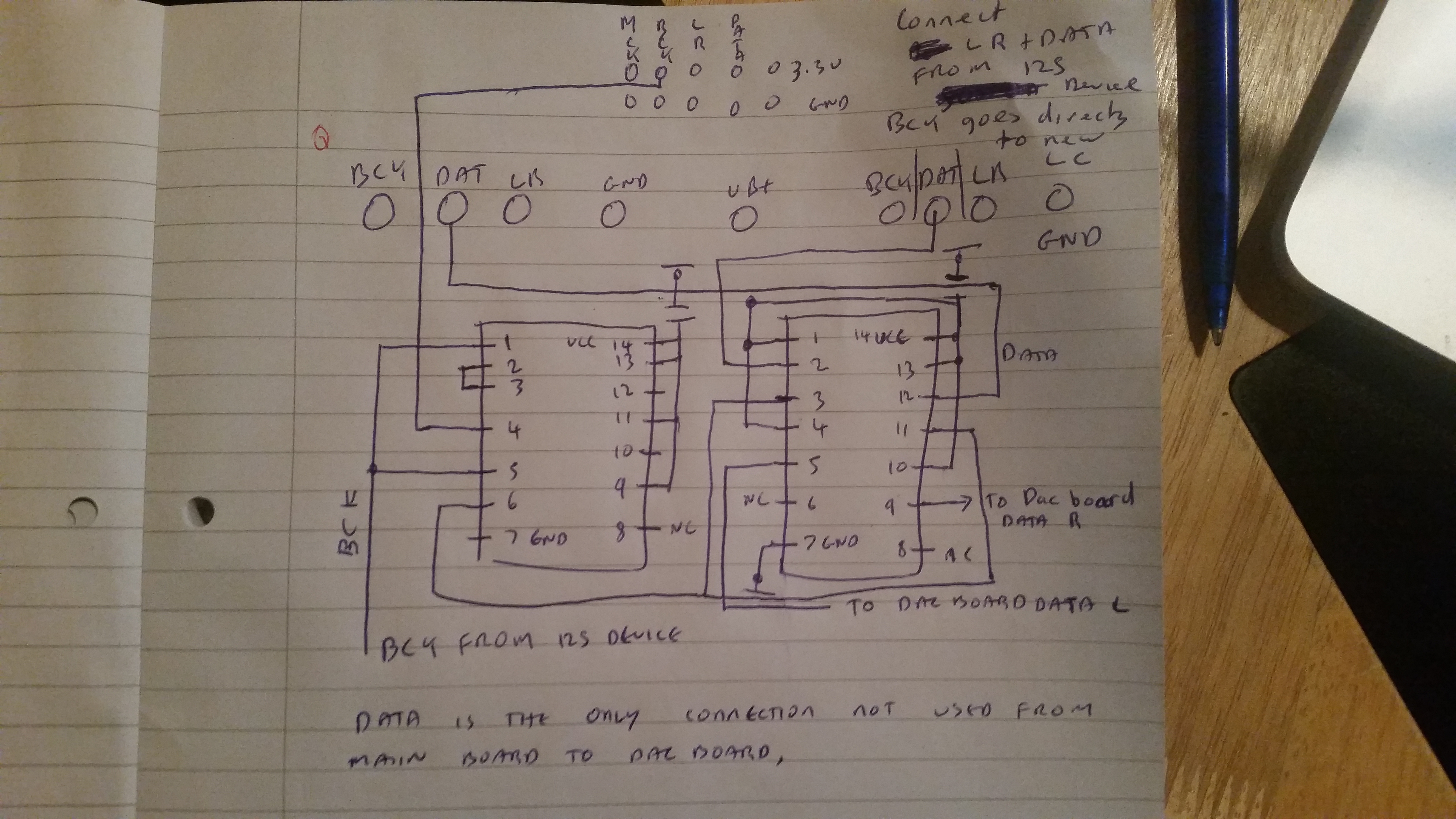
yea heres the poorest offer of a diagram youve ever seen
you can put in the decoupling r's but i dint think they were necessary
its mostly just to explain how bck lr and data is wired


Hey James, WoW! You have been busy!
I have upgraded to Blue Mainboard and now the Green became surplus. They way it seems, I might as well getting another DAC board and join this fun/game with you guys.
On unregulated ps, has anyone try CLCLC? I did it last-night and found not to my preference post exposure to Choke input configuration. CLCLC gave me a dry sound, micro detail dynamic suddenly veiled, and more punchy bass but not realistic. Can someone please tell me the appropriate input raw vdc for 3.3V and 5V shunts on Main-board? As for 8V shunts, I have input voltage right at their input leg is 12.5VDC and approx 9VDC at the leg of 3.3V shunts. These are made specific for Doede's DAC, I wonder if the Tent Lab shunt's manual for input voltage is still applicable? Stijn - do you have any idea, please?
Cheers.
I posted a while back about using smd film caps and working well for me
Which may only work for me because of the lifepo4 ps feeding the 1794 chips
But to be honest it wasn't a huge area of improvement
Maybe ZM has something else in mind?
really nothing - maybe "just" fiddling with cap value , if that already wasn't done
.. Can someone please tell me the appropriate input raw vdc for 3.3V and 5V shunts on Main-board? As for 8V shunts, I have input voltage right at their input leg is 12.5VDC and approx 9VDC at the leg of 3.3V shunts. These are made specific for Doede's DAC, I wonder if the Tent Lab shunt's manual for input voltage is still applicable? ..
Chanh, all and all I think you are a bit on the high side on both the digital and analogue sides. The bigger the voltage difference the more the shunts will need to drop and the hotter they will get.
I would aim for 6-8V measured at the digital shunt and 10.5-12V at the analogue.
In mine, I measured 10.3V at the analogue shunts initially, which worked fine, but I cranked it up to 10.6V to be on the safe side.
Last edited:
Cheers Guys for the inputs!
I have a very respectable audio friend dropping by today assisting me with my new speakers positioning. He is too well familiar to my setup, inside out. The moment he walked into the room without actually sit at the sweet spot, he made the comments "Wow!! The dynamic...! Anyone should be extremely proud with this result but now I feel the rest of ya chain are the bottleneck!"
Btw, this guy is full on Vinylphile and anti-digital, and to have such comments from him was simply full of joys and rewarding. Thanks again to Doede and All with ya enthusiasm in tweaking, advancing the DAC closer to an Analog alike sonic signature. Love it!
You mean you're getting solder fume withdrawal symptoms?I might as well getting another DAC board and join this fun/game with you guys.
You must be very pleased after all that work"Wow!! The dynamic...! Anyone should be extremely proud with this result but now I feel the rest of ya chain are the bottleneck!"
What kit is in the rest of your chain?
Nige2000,
Do have a picture of your 1/2 clock chips installation? What did you use for an adapter board?
Thanks
i unfortunately shoehorned them to a ssop adapter boards its a complete mess a pic will likely confuse further
i got some of these to tidy it up
SMT SMD DIL Adaptor Soic 16 PIN Narrow W Ground Plane | eBay
You're doing pretty well when you get to the stage where that kit's a bottleneck!James,
Am a Valves kinda guy, unless classA Vitus or Gryphon. I have Conrad Johnson PreAmp, Bob Carvers Cherries powerAmps, Wilson Benesch Speakers.
Looks like a plan. For the 2 extra chips, the schematic lists them as 74vhc74mx and 74vch04mx but I can't find any parts that end with an x. Did you use 74vhc74m and 74vch04m?i unfortunately shoehorned them to a ssop adapter boards its a complete mess a pic will likely confuse further
i got some of these to tidy it up
SMT SMD DIL Adaptor Soic 16 PIN Narrow W Ground Plane | eBay
You're doing pretty well when you get to the stage where that kit's a bottleneck!
Looks like a plan. For the 2 extra chips, the schematic lists them as 74vhc74mx and 74vch04mx but I can't find any parts that end with an x. Did you use 74vhc74m and 74vch04m?
this is what i used
74VHC04M - FAIRCHILD SEMICONDUCTOR - 74VHC CMOS, SMD, 74VHC04, SOIC14 | Farnell Ireland
74VHC74M - FAIRCHILD SEMICONDUCTOR - 74VHC CMOS, SMD, 74VHC74, SOIC14 | Farnell Ireland
- Home
- Source & Line
- Digital Line Level
- A NOS 192/24 DAC with the PCM1794 (and WaveIO USB input)