I ran 5 different CCS circuits on a breadboard
Very intresting, great effort. But what's not clear to me is that you are measuring mV, while we want to know mA.., or is the last comment w.r.t 5mV increments a type-O (although you menation current in all other places.). Sorry if I'm nitty picking..(i'm usually the one making all tht type-O's)
However I'm not convienced it's realistic represesntation of what the dac chip is doing to fluctuate 5mV at 10KHz. I thought we'd estblished it was a pretty constant 2.4V.
It would be intresting to hook the scope up to the dac pin 20 and put a 10Khz audio signal on it and see what portion of it shows up on pin 20 to see the impact on the real behavior agianst your current measurements.
There must be a mV fluctution at pin-20 otherwise no SQ gain would be heard swapping out the resistor for a CCS..
")
Last edited:
On the multimeter pin 20 is constantly 2.4v no matter what the analogue v, ccs current, vcom output bias is etc etc
I've been playing with it
The ccs current value doesn't directly have an effect on sq
But it has an indirect effect on vcom and output bias which does matter
Suppose I should put it on the scope
I've been playing with it
The ccs current value doesn't directly have an effect on sq
But it has an indirect effect on vcom and output bias which does matter
Suppose I should put it on the scope
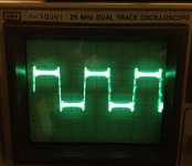
I ran 5 different CCS circuits on a breadboard with all devices set for .406ma and a signal source of 2.46V which duplicates the DDDAC with a 6.04K resistor. A 0.5v 10khz square wave was imposed on the 2.46V source signal. The scope input was from a 100 ohm resistor between the CCS device and ground or as the bottom 100 ohms of the resistance of the CCS circuit to ground. From left to right the Scope displays are:
1. 6.04K resistor
2. JFET
3. Cascoded JFET
4. LM334 with tempco
5. JFET with 22uf cap across the source resistor
The only device without any overshoot spike is the 6.04k resistor, but we all know that it provides the least favorable sq. It also has the most variation in current.
The device with the most severe overshoot spiking is the LM334, but it also provides the most constant current. This same device with a 10K sine wave displays a perfectly flat line. I don't know what kind of signal is present at pin 20, but if the signal changes are well within the transient response time of the LM334 then this CCS may sound great.
I used a TO-92 plastic LM334. I measured 0.596V across the 1N457 diode. I had to adjust the R1 resistance to 340 ohms and R2 to 3.4K to get the current I needed. 330 ohms gave me 4.16ma which may be ok too.
The least amount of spiking in an active device is the cascoded JFET which I am listening to right now with about 300 hours of play time. Very neutral, detailed, and authoritative compared to the 6K resistor. Current variation is almost flat on the scope.
The single JFET CCS shows a little more spiking and the current varies a little with input signal. I want to test this CCS some more because in my limited testing with a prototype board there was an extra excitement and 3 dimensional presentation of the music. I need to know what it sounds like after a 300 hour burnin.
Adding a source resistor bypass cap to the JFET adds a component with worse scope displays compared with the JFET. I'm dropping this from further consideration.
I need to learn how dwjames drops pictures into the middle of the test.
The scope was set for 5mv/division. The hazy band across the display is there with inputs shorted. I had to increase the intensity to make the spikes more visible.
Excellent work, Ross - thank you for putting together these results.
In my book, the cascoded JFET configuration is typically a top choice (I'm using it in most of my LV mods, together with cascoded depletion-mode MOSFETs for HV applications; they both perform excellent), though I'm weary of the very low voltage here - 2.4V - over the assembly. Your plot though indicates very good behavior.
Radu.
The voltage measurement across a resistor is a current measurement, V=IR. I adjusted each CCS circuit so that the voltage across the 100 ohm resister was 40.6mv or 0.406ma.
If pin 20 operated at a rock steady 2.4VDC, then we would hear no difference replacing the 6K resistor with a CCS - but the change in SQ is significant and probably different with each CCS design. I'm sure that the 0.5V 10 KHz from my signal generator is more severe to these CCS circuits than what pin 20 is putting out, but it allows us to differentiate the potential performance of each CCS device.
I hope someone will put a scope on pin 20 into a resistor and display it on the forum. I downloaded a free program called Sweepgen which I use to adjust my DSP equalizer for my speakers. Music would generate random signals at pin 20 whereas a single frequency from Sweepgen should produce a repeatable signal which could be captured on a Scope. Sweepgen worked fine through my WaveIO card.
On the multimeter pin 20 is constantly 2.4v no matter what the analogue v, ccs current, vcom output bias is etc etc
the obvious question is how you measured - ac over dc?... depending on your DMM you may have different provisions on how ac riding on dc can be measured
I've been playing with it
The ccs current value doesn't directly have an effect on sq
But it has an indirect effect on vcom and output bias which does matter
Suppose I should put it on the scope
a scope pic would be great
On a different note, I see the newer blue main board has a couple of extra logic chips rather than using resistors to delay the i2s signal. Is that a known improvement?
Does anyone have a straightforward method for retrofitting these 2 chips to the older red main board?
Does anyone have a straightforward method for retrofitting these 2 chips to the older red main board?
Scope Pin 20
I put a scope on pin 20 feeding a cascoded CCS and also a 6.04K resistor.
The scope pictures didn't show much because the signals smeared together, but this is what I saw.
1. Scope displays showed a variation of what looked like a blend of periodic and random sine waves varying by no more than +/- 5mv. Nothing that resembled square waves, but the sine waves sometimes appeared distorted.
2. The clearest sine waves were displayed at 0.5usec time/div. These could be clock signals or digital noise from the DAC. There were also smeared sine waves at 10usec time/div.
3. Interestingly, the signals for the CCS were about twice as large as the ones for the 6K resistor. I guess this makes sense because a CCS allows the voltage to float without any change in current.
4. The signals were slightly more messy looking with a 1 KHz square wave being fed into the DAC versus no signal being fed.
There is something going on at pin 20 besides a steady 2.4VDC, but the variations are small and at high frequencies. This doesn't tell me what to do but to continue to do listening tests.
Just for fun I scoped the RCA output for the 1 KHz signal. This proves that I was actually putting a signal through the DAC. Maybe someone else can get more definitive scope displays from pin 20.
Attachments
PET-240: "I think that it was discussed, but perhaps an Oscon across the CCS to decouple it?"
My hunch is that if a capacitor from pin 20 to ground helped the performance of the PCM1794 that it would be in the data sheet suggested applications circuits.
This can by tried on the 6K resistor. Let us know how it sounds.
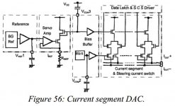
if logic from attached picture is applicable (I didn't got source of that schematic ) - fiddle with pin 21 an 22 decoupling (Vcom pins) , not pin 20
it's pretty much irrelevant observing what's happening on pin 20 in AC domain; in fact - greater amplitude probably means that servo is working more effectively
it's pretty much irrelevant observing what's happening on pin 20 in AC domain; in fact - greater amplitude probably means that servo is working more effectively
Attachments
PET-240
There is no such thing as a stupid question, but there is an unlimited supply of stupid answers.
Natural stupidity usually beats artificial intelligence.
I've done it ill draw a diagram and post laterOn a different note, I see the newer blue main board has a couple of extra logic chips rather than using resistors to delay the i2s signal. Is that a known improvement?
Does anyone have a straightforward method for retrofitting these 2 chips to the older red main board?
That would be brilliant, thanks.I've done it ill draw a diagram and post later
I had a quick ponder over the 2 versions if the mainboard schematics today at lunch and it looks reasonably straightforward, but I couldn't quite make a direct comparison as I don't exactly understand what happens with the bclk out of the new i2s/spdif switching chip, so a diagram would answer all my questions there.
Cheers
On a different note, I see the newer blue main board has a couple of extra logic chips rather than using resistors to delay the i2s signal. Is that a known improvement?
Does anyone have a straightforward method for retrofitting these 2 chips to the older red main board?
I asked this question months ago and did not get an answer from Doede.
I wonder if it has something to do with the SPDIF input? But have no idea.
Maybe with two asking we will be told?
if logic from attached picture is applicable (I didn't got source of that schematic ) - fiddle with pin 21 an 22 decoupling (Vcom pins) , not pin 20
it's pretty much irrelevant observing what's happening on pin 20 in AC domain; in fact - greater amplitude probably means that servo is working more effectively
That would be something if THAT is where the real action is!
ZM do you have any idea what could be an improvement over a capacitor?
I know I do not know!
I posted a while back about using smd film caps and working well for meThat would be something if THAT is where the real action is!
ZM do you have any idea what could be an improvement over a capacitor?
I know I do not know!
Which may only work for me because of the lifepo4 ps feeding the 1794 chips
But to be honest it wasn't a huge area of improvement
Maybe ZM has something else in mind?
Last edited:
There's 4 extra chips on the newer blue 'S' mainboard, 1 is the spdif driver, 1 is to handle the switching between i2s and spdif, but then there are 2 extra chips and it's these I'm interested in.I asked this question months ago and did not get an answer from Doede.
I wonder if it has something to do with the SPDIF input? But have no idea.
Maybe with two asking we will be told?
On each dac deck there are 3 series resistors through which the data and clock signals flow.
With the older red main board, the resistor on the 'data' line is 1k. In Doede's documentation he says
Doede said:The inputs are connected through the decouple resistors R5-7. R6 is 1kOhm to add some extra delay, to compensate for the extra 1/2 clock cycle in the delay section due to the VHC164 clock function [\QUOTE]
But with the new Red mainboard, it seems this extra delay is handled by those 2 extra logic chips and the decouple resistor recommended for each deck's data line is 100r to match the other 2.
It's these 2 chips underneath here
An externally hosted image should be here but it was not working when we last tested it.
I don't think it's any secret, it's all there in the schematics. I assume the logic chips make a more accurate job of providing this delay, but I'm only guessing.
I'm not trying to tread on anyone's toes or to take any sales away from Doede. If I was going to use the spdif input with its ability to add a nice clock and the neat led indicator breakout board, I'd definitely update to the new version of the mainboard, but I don't (for now at least) so I wonder if this is a design/performance improvement and if I could simply retrofit it myself.
- Home
- Source & Line
- Digital Line Level
- A NOS 192/24 DAC with the PCM1794 (and WaveIO USB input)