ok, so 1 last look at the lm334 datasheet and it makes more sense now.That's odd...
Rax, a TO-92 LM334Z looks far easier to deal with, thanks for the tip !
The resistor values appear to be independent of voltage, so they are fairly simple calculations based on the characteristics of the lm334 and the voltage drop of a 1n457 resistor.
They quote a standard 1 resistor temperature sensitive setup to give 1ma
An externally hosted image should be here but it was not working when we last tested it.
And then give an example for 1ma with a 2 resistor and diode, zero tempco version
An externally hosted image should be here but it was not working when we last tested it.
So, R1 is 68r to give 1ma with the simple tempco circuit and 134r to give 1ma with the zero tempco circuit. So in very rough terms, we can expect r1 for zero tempco to be around double that of the normal tempco setup.
An externally hosted image should be here but it was not working when we last tested it.
So Iset (the current you're trying to set) is just 0.134 divided by the resistance as this 0.134 figure is determined by the parts used, so is relatively constant (assuming the voltage drop of the diode is accurate)
In their example :
0.134 / 134r = 0.001A = 1ma
In our assumed r1 = 165 setup:
0.134 / 165r = 0.000812 = 0.8ma
Which is roughly what I measured last night.
But if we want 0.4mA...
0.134 / 330 = 0.000406 A = 0.4mA
And if r1 = 330r, r2 = 3k3r
Makes sense to me finally...
It makes sense to me too.
This way i'm ordering 332 and 3.32k 0.1 %
The 1N457 diode remains, right ?
Anyway i've put my new trafo in place, a 200 VA EI-core (didn't expect it to be so big and heavy) with 2*16V secondaries and a screen.
The music is airier, ans the bass stronger. I could still afford some more layering and instrument separation, but I guess the next works will bring some.
Yes, the 1n457 diode remains as this gives the 0.6v voltage drop and the 1:10 ratio which makes the resistor calculations 'simple'..It makes sense to me too.
This way i'm ordering 332 and 3.32k 0.1 %
The 1N457 diode remains, right ?
Anyway i've put my new trafo in place, a 200 VA EI-core (didn't expect it to be so big and heavy) with 2*16V secondaries and a screen.
The music is airier, ans the bass stronger. I could still afford some more layering and instrument separation, but I guess the next works will bring some.
Good news on the new trafo
")
It's a bit clunky how I've done it, but it works.James, have you got a link for the stackable sockets/pins? Can only seem to find full header pin sets.
I used these, which you can find by searching eBay for 'arduino stackable'
http://pages.ebay.com/link/?nav=item.view&id=251611671987&alt=web
Then I just cut the plastic off with some side cutters so I was just left with the pins
The ones on the main board are just regular PCB header sockets, but do try and get the rolled ones with round holes, as they seem to connect nicer and work ok singularly. Ones which look like this

Last edited:
transformer stories
Hello my French audiophile,
I already did tell you many times that toroidal transformers are usually not that good for audio. And especially with digital gear a screen is a big plus.
Start reading the magazines from '' l'' audiophile '' Yes the one in French. I have the original paper ones but can be found on the internet too.
Greetings, Ed
It makes sense to me too.
This way i'm ordering 332 and 3.32k 0.1 %
The 1N457 diode remains, right ?
Anyway i've put my new trafo in place, a 200 VA EI-core (didn't expect it to be so big and heavy) with 2*16V secondaries and a screen.
The music is airier, ans the bass stronger. I could still afford some more layering and instrument separation, but I guess the next works will bring some.
Hello my French audiophile,
I already did tell you many times that toroidal transformers are usually not that good for audio. And especially with digital gear a screen is a big plus.
Start reading the magazines from '' l'' audiophile '' Yes the one in French. I have the original paper ones but can be found on the internet too.
Greetings, Ed
Also, this week i installed some header sockets in the main board and long arduino stacking header pins in my dac deck.
This means I can easily remove and refit my dac board if I want to try stuff.An externally hosted image should be here but it was not working when we last tested it.An externally hosted image should be here but it was not working when we last tested it.
So I decided to test out if a DAC deck with just Oscons would work well with the shunts
An externally hosted image should be here but it was not working when we last tested it.
I can't fault the detail of the sound, but I found it somehow grated on me and I wasn't relaxing listening to it.
So I swapped the all but the vcom and the cap closest to the digital reg out for Silmic II this evening. I also did the main board caps and put a small OSCON directly on the input of the main board reg
An externally hosted image should be here but it was not working when we last tested it.An externally hosted image should be here but it was not working when we last tested it.An externally hosted image should be here but it was not working when we last tested it.
Much better
In other news, I'm also trying out a prototype jfet buffer stage to go in between the balanced outputs and my cinemag transformers. Man, that case is getting full and heavy now!
An externally hosted image should be here but it was not working when we last tested it.An externally hosted image should be here but it was not working when we last tested it.
It's early days as it's burning in, but so far I'm impressed
excellent work, James, through and through. Just a quick word to salute your focused and informed pursuit of this group's goals...
Radu.
And if r1 = 330r, r2 = 3k3r
Makes sense to me finally...
Ok, that's different. I'll have a look at the sheet agian as well, means I have he wrong parts too..
Thanks and thanks for your help too. I still feel that compared to most here, my knowledge of electronics and audio is minimal. But I really love the learning and the doing and I find out what I can by reading, practical tests and by asking stupid questionsexcellent work, James, through and through. Just a quick word to salute your focused and informed pursuit of this group's goals...
Radu.
So when I get to the stage where I have found out enough to mean I understand something in simple terms, it's nice to give something back and share those simple explanations.
Also, I've recently discovered the tapatalk phone app, and that makes it incredibly easy to share pictures here, so it's really no hassle
I had a quick look earlier and I have enough random spares here to make 331r and 3k3, so I can hopefully find out for sure later this evening. I'll let you know how I get on.Ok, that's different. I'll have a look at the sheet agian as well, means I have he wrong parts too..
Adventures in lm334 continue...
With just the 165r resistor I get current of 405uA at room temperature going up to about 500uA if I blast it with a hairdryer.
So I swapped to the zero tempco of 330r r1, 1n457 diode and 3k3 r2 using bits from spares box. This gave me current of 415uA going up to 430uA with the hairdryer treatment. So much less rise, but certainly not zero...
Points to note:
The current isn't relative to the input voltage, so it's easy to test with a 9v battery for example.
I think that the zero tempco calculation wasn't more effective here because I used the standard calculation from the datasheet which assumed my diodes had a drop of 0.6v, but I measured 0.699v on both of them with my meter. Maybe 1n457 has changed spec or there are a few versions and mine have 0.7v drop?
But it's all good. I have more resilience to temperature rises now and it's working nicely again and sounding great.
With just the 165r resistor I get current of 405uA at room temperature going up to about 500uA if I blast it with a hairdryer.
So I swapped to the zero tempco of 330r r1, 1n457 diode and 3k3 r2 using bits from spares box. This gave me current of 415uA going up to 430uA with the hairdryer treatment. So much less rise, but certainly not zero...
An externally hosted image should be here but it was not working when we last tested it.
An externally hosted image should be here but it was not working when we last tested it.
Points to note:
The current isn't relative to the input voltage, so it's easy to test with a 9v battery for example.
I think that the zero tempco calculation wasn't more effective here because I used the standard calculation from the datasheet which assumed my diodes had a drop of 0.6v, but I measured 0.699v on both of them with my meter. Maybe 1n457 has changed spec or there are a few versions and mine have 0.7v drop?
But it's all good. I have more resilience to temperature rises now and it's working nicely again and sounding great.
CCS Oscope tests
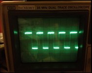
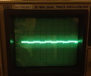
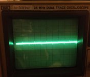
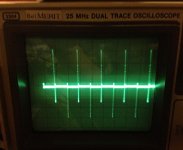
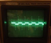
I ran 5 different CCS circuits on a breadboard with all devices set for .406ma and a signal source of 2.46V which duplicates the DDDAC with a 6.04K resistor. A 0.5v 10khz square wave was imposed on the 2.46V source signal. The scope input was from a 100 ohm resistor between the CCS device and ground or as the bottom 100 ohms of the resistance of the CCS circuit to ground. From left to right the Scope displays are:
1. 6.04K resistor
2. JFET
3. Cascoded JFET
4. LM334 with tempco
5. JFET with 22uf cap across the source resistor
The only device without any overshoot spike is the 6.04k resistor, but we all know that it provides the least favorable sq. It also has the most variation in current.
The device with the most severe overshoot spiking is the LM334, but it also provides the most constant current. This same device with a 10K sine wave displays a perfectly flat line. I don't know what kind of signal is present at pin 20, but if the signal changes are well within the transient response time of the LM334 then this CCS may sound great.
I used a TO-92 plastic LM334. I measured 0.596V across the 1N457 diode. I had to adjust the R1 resistance to 340 ohms and R2 to 3.4K to get the current I needed. 330 ohms gave me 4.16ma which may be ok too.
The least amount of spiking in an active device is the cascoded JFET which I am listening to right now with about 300 hours of play time. Very neutral, detailed, and authoritative compared to the 6K resistor. Current variation is almost flat on the scope.
The single JFET CCS shows a little more spiking and the current varies a little with input signal. I want to test this CCS some more because in my limited testing with a prototype board there was an extra excitement and 3 dimensional presentation of the music. I need to know what it sounds like after a 300 hour burnin.
Adding a source resistor bypass cap to the JFET adds a component with worse scope displays compared with the JFET. I'm dropping this from further consideration.
I need to learn how dwjames drops pictures into the middle of the test.
The scope was set for 5mv/division. The hazy band across the display is there with inputs shorted. I had to increase the intensity to make the spikes more visible.
Attachments
Top work Sir!I ran 5 different CCS circuits on a breadboard with all devices set for .406ma and a signal source of 2.46V
That certainly shows up the lm334 as not ideal in that test, but as you say, how does that translate in terms of sound?
Have you been able to scope the pin20 output with music playing to get an idea of what the typical real world voltage variation is?
Look forward to your observations on the sound of the other options
- Home
- Source & Line
- Digital Line Level
- A NOS 192/24 DAC with the PCM1794 (and WaveIO USB input)