Hi Ian,
would it be possible to get the I2StoPCM board to output signals to dual TDA1543 as described in this messages?
http://www.diyaudio.com/forums/digi...e-nos-dac-using-tda1541a-536.html#post4247252
Dual TDA1543, quasi simultaneous mode
http://www.diyaudio.com/forums/digi...e-nos-dac-using-tda1541a-579.html#post4924235
BUMP

I would be very interested in using TDA1543 with this board

BUMP
I would be very interested in using TDA1543 with this board
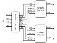
I think you would connect the 1543s same as two 1541, but send left data (Dl) to the R channel of one, and right (Dr) data to the other's R channel.
See image.
You could also use 4x 1543, sending inverted data to to the right inputs of the second pair so you would have a balanced output.
Attachments
I think you would connect the 1543s same as two 1541, but send left data (Dl) to the R channel of one, and right (Dr) data to the other's R channel.
See image. http://www.diyaudio.com/forums/attachment.php?attachmentid=700125&d=1535450457
You could also use 4x 1543, sending inverted data to to the right inputs of the second pair so you would have a balanced output.
Sorry, but look at that small extra pin 27 labeled -5 volt
This brings the 1541 in PCM mode. The 1543 does not have the PCM mode capability.
But once there was a TDA1543A and that other version did have a pcm input or something japanese. So you could look for that part.
Sorry, but look at that small extra pin 27 labeled -5 volt
This brings the 1541 in PCM mode. The 1543 does not have the PCM mode capability.
But once there was a TDA1543A and that other version did have a pcm input or something japanese. So you could look for that part.
Why does this matter? You are only using the right channel of the 1543 so both left and right channel data is latched into the two 1543s right channel at the same time.
Last edited:
If I am right (?) the PCM also inverts the datasequence from left aligned to right aligned.
With standard Philips I2S you can just throw 32 bits at the 16 bit chip - once the buffer has read the first 16 it descards the rest,
whith PCM it is in the 'wrong' sequence, you have to send all bits you use (which makes that programming of Ian's PCM board with pins so essential).
With standard Philips I2S you can just throw 32 bits at the 16 bit chip - once the buffer has read the first 16 it descards the rest,
whith PCM it is in the 'wrong' sequence, you have to send all bits you use (which makes that programming of Ian's PCM board with pins so essential).
If I am right (?) the PCM also inverts the datasequence from left aligned to right aligned.
With standard Philips I2S you can just throw 32 bits at the 16 bit chip - once the buffer has read the first 16 it descards the rest,
whith PCM it is in the 'wrong' sequence, you have to send all bits you use (which makes that programming of Ian's PCM board with pins so essential).
You could be right. I didn't consider the data format. I believe I2S uses Twos complement MSB first, but I don't know what format Ians board outputs, or the 1541 in simultaneous mode requires. As its PCM I assume it is just plain 16bit serial data so the 1543s won't be happy.
If I am right (?) the PCM also inverts the datasequence from left aligned to right aligned.
With standard Philips I2S you can just throw 32 bits at the 16 bit chip - once the buffer has read the first 16 it descards the rest,
whith PCM it is in the 'wrong' sequence, you have to send all bits you use (which makes that programming of Ian's PCM board with pins so essential).
I think that only is true for the TDA1541 jumper setting on Ians board. All the mono dacs (pcm170X pcm 6X ad1862) accepts I2S as input format. The real problem here is that they accept more than 16 bits, so the clock is not stopped as long time as it could and that TDA1543 latches the output on the first clock after WS has gone low, so we need to start the clock at some point again (and stop it again after 1 clock pulse) while the WS is low in order to get anything to the outputs.
problem with i2s to pcm
It has stopped working, fifo reclocker and dualxo work correctly, but the led i2s does not turn on. When done some tests the led was turned on when the i2stopcm was turned on (the dac) but immediately the led i2s was turned off, now it does not turn on anymore. I think he died. Any idea what I can do?
Ian, is it possible to buy an i2stopcm?
Can someone sell me one?
regards
Thanks Ian for the quick response.
I have reviewed the connections several times, and I have changed the connector to the dualxo (J3). I had some problem with this from the beginning, I thought there was no weld UFL connectors, but yesterday I removed them and connected J3 to dualxo, but it does not work either. In dualxo and fifo all leds it's OK.
Best regards.
I will ask you for a new one.
Hi, it is sure that my DAC has had an electrical problem and has been damaged not only the I2STOPCM, also the FIFO PCB. I tried separately and both fail, I could not try Dualxo to see if it fails, in principle all LEDs are lit correctly, so far I have already ordered a Fifo board and another I2STOPCM.
Best Regards
Best Regards
I2S to PCM bit accuracy I/O TDA1541A
Dear Ian,
Is it true that your (my) I2S to PCM board is not best suited 'as is' to TDA1541A ?
https://www.diyaudio.com/forums/dig...e-nos-dac-using-tda1541a-667.html#post5570744
Kind regards,
Hanze
Dear Ian,
Is it true that your (my) I2S to PCM board is not best suited 'as is' to TDA1541A
?https://www.diyaudio.com/forums/dig...e-nos-dac-using-tda1541a-667.html#post5570744
Kind regards,
Hanze
Last edited:
PCM board works with TDA1541/A perfectlly at simultaneous mode.
Please keep in mind, for PCM board, input format other than true I2S will cause wrong sound of music. For example, the Sony format, which can be found in many CD players that were made in Japan.
Somebody thinks that the timing of PCM board looks different to the timing in datasheet. Yes, it’s true. But it’s not a mistake. Different from other TDA1541/A drivers, PCM board works in synchronized timing mode. It was originally designed in that way trying to eliminate more noise from PCM timing. Both timing in the TDA1541 datasheet and the timing of my PCM board are within the timing restriction. TDA1541/A has no problem working with either of them. But theoretically the timing of PCM board will bring less noise to the TDA1541 DAC.
I did some test again last weekend to double confirm PCM board works with TDA1541/A at simultaneous mode. Here are details of the test:
I did some test again last weekend to double confirm PCM board works with TDA1541/A at simultaneous mode. Here are details of the test:
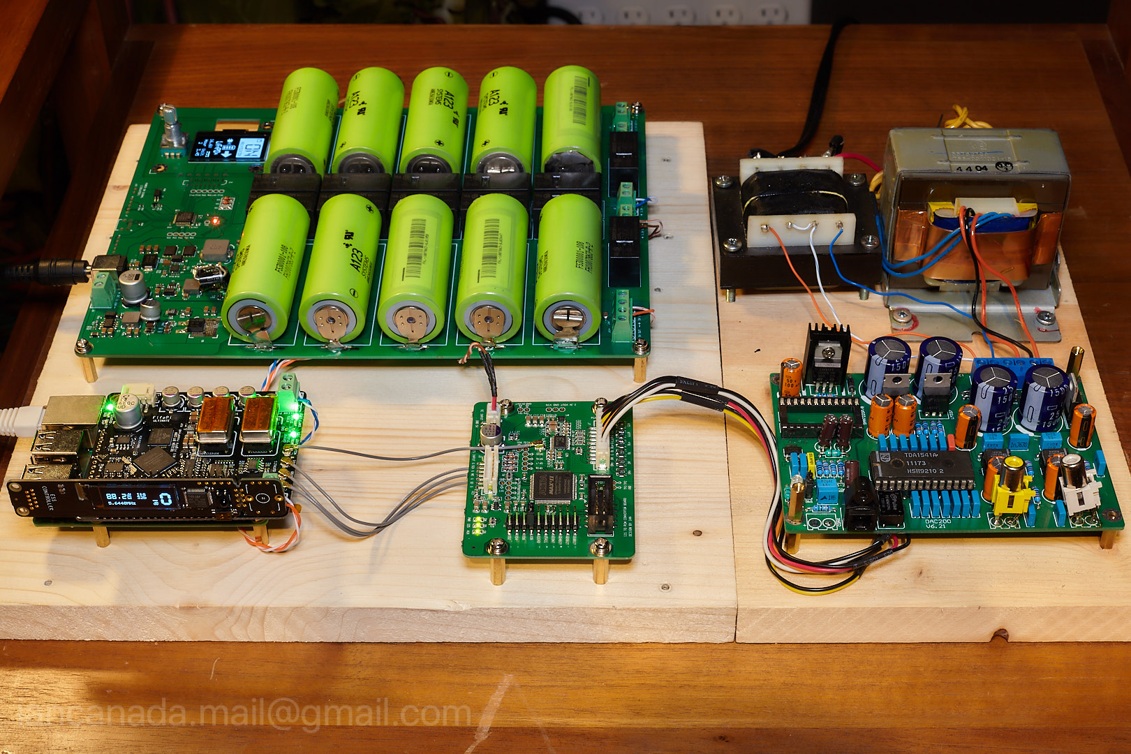
1. Configurations:
RPi with Volumio as player,
FifoPi with 45/49MHz XOs
Real time music format monitor by an ESS DAC controller
PCM board
TDA1541A DAC
LifePO4 pure power supply
2. Music format for test
44.1KHz 16bit
44.1KHz 32bit
88.2KHz 32bit
192KHz 32bit
3. PCM board jumper settings
JOB: jumped (short)
HALF SPEED: short or open
4. Testing result
All above music formats were tested working with TDA1541A DAC perfectly without any problem. Sound quality was amazing with the battery based power supply included in system. TDA1541A plays at its signature style comparing with other Delta-Sigma DACs. Full speed mode feels a little bit better than half speed, (might be caused by more silence time within PCM timing).
Please keep in mind, for PCM board, input format other than true I2S will cause wrong sound of music. For example, the Sony format, which can be found in many CD players that were made in Japan.
PCMboardTDA1541Configuration
by Ian, on Flickr
Attachments


Last edited:
Somebody thinks that the timing of PCM board looks different to the timing in datasheet. Yes, it’s true. But it’s not a mistake. Different from other TDA1541/A drivers, PCM board works in synchronized timing mode. It was originally designed in that way trying to eliminate more noise from PCM timing. Both timing in the TDA1541 datasheet and the timing of my PCM board are within the timing restriction. TDA1541/A has no problem working with either of them. But theoretically the timing of PCM board will bring less noise to the TDA1541 DAC.[/FONT][/COLOR]
Hi Ian,
Since it works, its for the doubters to accept this. Anyone else like myself who has had issues have probably been sending it the wrong format of data.
Am I right in thinking when used with your FIFOII board, I can input the other pcm formats? The instructions imply this is possible with jumpers 4 & 5.
I'd really like to use my Denon Professional Rack Mounting CD player as it has a 'quality feel' to the buttons, Sanyo transport and all steel construction.
Any news on my faulty board? (my fault in connecting it to 15v instead of 5v)
Long time ago i got the TDA1541 working with a PMD-100 digital filter (with additional glue logic) in simultaneous mode. Also outside the timing restrictions shown in the 1541 datasheet. It works.
Don't ask me how it "sounds", never completely finished the project (still on my to-do list, which is long).
Don't ask me how it "sounds", never completely finished the project (still on my to-do list, which is long).
Some timing diagrams from a long time ago.

Signals are (top to bottom):
LR and BCI: the input to the PMD100 (modified I2S)
BKO, DOL and WCK: the output of the PMD100 (BKO is a typo, should be BCO).
LE is the pulse made by converting WCK
DG is the de-glitch signal, reclocked it becomes DEM.

Picture two shows one frame of BCKO, DOL and WCKO. The LE signal is the one used to latch the TDA1541, it latches on the rising edge.

Last one zooms in on LE, DG and DEM.
Signals are (top to bottom):
LR and BCI: the input to the PMD100 (modified I2S)
BKO, DOL and WCK: the output of the PMD100 (BKO is a typo, should be BCO).
LE is the pulse made by converting WCK
DG is the de-glitch signal, reclocked it becomes DEM.
Picture two shows one frame of BCKO, DOL and WCKO. The LE signal is the one used to latch the TDA1541, it latches on the rising edge.
Last one zooms in on LE, DG and DEM.
Last edited:
Hi Ian
Thanks for making this board available to the aficionados of old Dac chips! Allow me to make reference to the discussion surrounding the implementation of the PCM protocol for the TDA1541a.
The way it is implemented now does sound well, as you have tested for yourself. However; it is true that the TDA1541a shifts data to the register when the LE signal goes positive. In the case of the I2S-to-PCM board that means that the data is shifted after 15bits have been recieved; turning the TDA1541a in fact into a 15bit Dac.
Don't get me wrong; it sounds lovey like that. It even sounds lovely when being used as a 14bit Dac, see here.
However, it does sound better as a 16bit Dac, especially when being fed with a 44.1khz signal.
I would like to motivate all those who use an I2S-to-PCM board with a TDA1541a to try the following:
(1) Feed your Dac with a 44.1 khz signal (non-oversampled) and listen carefully to get an impression.
(2) Disconnect the LLLR out of the I2S-to-PCM board.
(3) Split the WS signal that goes into the I2S-to-PCM board and feed it both into the I2S-to-PCM (WS in) and also into the Latch Enable input of the TDA1541a. If you have a McFIFO just take a second u-fl cable and connect another WS out of the clock board to the LE in of the TDA1541a.
(4) Listen to some music and see if you notice the difference; specifically at 44.1khz.
In the case of my AYA Dac the difference was not subtle. Before the mod described above the heights sounded so recessed and muffled when feeding a 44.1khz signal that I contacted Pedja because I thought that my DAC was faulty. Oversampling in SOX to 88.2 or more solved that and clearly improved the sound. After the mod the music sounds brilliant at 44.1khz and with 44.1khz material I cannot hear a difference between a 44.1 and 88.2 or higher signal.
Without the mod feeding a 384khz signal to the TDA1541a produced silence - after the mod it produces heavily distorted sound - which is a kind of an improvement. It plays music with a 336khz signal in both setups. The fact that it does not work with a 384khz signal might be a hint that the timing of the BCK's rising/falling edge could still be optimized; since it has been shown that the TDA1541a can handle 384khz signals.
Ian, I understand that your efforts are currently focused on the battery/capacitor power supplies (which I am very much looking forward to). However, if you have some time and interest to look at the I2S-to-PCM board again, I would like to kindly ask you if you could change the TDA1541a settings according to the data sheet (DATA change on the rising edge of the BCLK and clocking it in at the falling edge of BCLK; then giving it a short pause before shifting the data to the register on the rising edge of LE). It should then be possible to max out the TDA1541a with a 384khz signal using your board.
Kind regards
ElEsido
Last edited:
- Home
- Source & Line
- Digital Line Level
- Drive NOS AD1865/62,PCM1704/02/63,TDA1541 from FIFO: Universal I2S-PCM driver board