Buzz off chris. I'm not asking anyone to design anything for me. I'm asking for layout advice on the new chip. You're continued ignorance and targeted presumptuousness is starting to **** me off. Keep to yourself please.Just how many threads are you going to pop up in asking people to design your commercial product for you?
If you made any attempt to understand the context of the situation you would know that doesn't apply here. Again, keep to yourself if all you are going to do is bash me the sake of it every time I ask a question.You can order any cheap CM6631A board and look at it, or buy their eval board, or look at pics. I can't remember but their eval board PDF manual may even have layer prints.
Edit: I just noticed the Pm39LV512 and SST39VF040-70-4C-WHE are the same pinout. You could have mentioned that without being a ****.
Last edited:
Thank you Kuba.
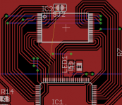
5th element's example seems to manage to keep all the traces on the same layer somehow, but maybe that's just the way it seems from the point of view of his picture.
Usually I try to keep digital lines on the same plane but if there is no issue with using multiple layers then I'll just do that.
Thanks again.
One more example from another forum:
http://bbs.hifidiy.net/thread-1379909-1-2.html
http://bbs.hifidiy.net/thread-1379909-1-2.html
Buzz off chris. I'm not asking anyone to design anything for me. I'm asking for layout advice on the new chip. You're continued ignorance and targeted presumptuousness is starting to **** me off. Keep to yourself please.
If you made any attempt to understand the context of the situation you would know that doesn't apply here. Again, keep to yourself if all you are going to do is bash me the sake of it every time I ask a question.
Edit: I just noticed the Pm39LV512 and SST39VF040-70-4C-WHE are the same pinout. You could have mentioned that without being a ****.
I apologize if I misconstrued your project.
I didn't mention it because I just assumed all those parts use the same pinout, which I guess is true.
There's probably no issue using vias and switching layers for this flash interface. I don't know what PCB layout tool you are using most can use design rules to ensure consistent trace/space for controlled impedance and also can ensure lengths are matched if you want to go to that extreme.
This layout guide is for a much faster flash memory, but it might be of some use:
https://www.cypress.com/file/276451/download
Last edited:
Thank you for the links and information regarding the firmware. I shall look into it when I get the time.
With regards to the traces to/from the flash memory. I use a bunch of zero ohm 1206/805 resistors to bridge across other traces as this helps to keep everything on the top side.
With regards to the traces to/from the flash memory. I use a bunch of zero ohm 1206/805 resistors to bridge across other traces as this helps to keep everything on the top side.
So as soon as I got this working I came down with the man flu hence the delay in posting an update.
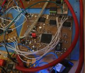
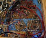
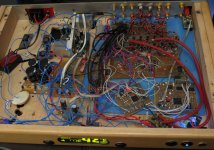
Pics are attached below.
The first thing I built was basically a proof of concept to check that it would work and wasn't really designed to be hooked up to a DAC/ADC. This update was designed for sound.
8 out, 2 in with isolation on the I2S streams. It's a shame that you can't get single chip USB2 480MB/s isolators...that would make isolation so simple.
Anyway I now have this working with multi-channel audio + a DSP. Multi-channel works great as does ASIO, so no issues there.
Now all that's left is to build the ADC. I've got an AK5578 waiting for stereo use. Lets see if it's actually any good.
Attachments
Hi Guys!
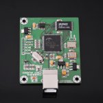
I have this cm6631 board from ebay. I like to change i2S BCK frequency, because it is 128*fs at 44,1 khz. I like to set it 64xfs all sampling frequency and SCK is 128xfs. Do you help me in it?
I download configuration tool, and i generate firmware new setting, but didnt update firmware. In firmware upgrade send firmware "upgrade error", i try many times. The original firmware is 0208. I have this firmware, I upgrade this firmware again.
NEW CM6631A DAC Board Digital interface card USB To IIS SPDIF Output 24Bit 192K | eBay
firmware problem
Hi Guys!
I have this cm6631 board from ebay. I like to change i2S BCK frequency, because it is 128*fs at 44,1 khz. I like to set it 64xfs all sampling frequency and SCK is 128xfs. Do you help me in it?
I download configuration tool, and i generate firmware new setting, but didnt update firmware. In firmware upgrade send firmware "upgrade error", i try many times. The original firmware is 0208. I have this firmware, I upgrade this firmware again.
Attachments
Hi,
Bob, can you upload to the board the previous firmware and it works correctly?
I had another strange problem: a new CM6631A PCB connected to Win10 and the system can not finish the installation. The first part runs correctly, the device is detected as a USB composite device, mass storage controller
with VID = 0D8C, PID = 5200. Unfortunately, this ends and during the next part of the recognition of the audio device there is a driver error and a message appears that the device has not been migrated. A similar situation is in WinXP in a different computer. CM6631A is not visible in the software to change the firmware and I can not upload a new one. Does anyone know the solution to the problem?
Hi Kuba!
I attached firmware. Is it work me on windows 7, it didnt try with other operation system.
https://drive.google.com/file/d/12VTQBC-oCnSvVS0rv5ku7UpPIh_0p9PH/view?usp=sharing
I attached firmware. Is it work me on windows 7, it didnt try with other operation system.
https://drive.google.com/file/d/12VTQBC-oCnSvVS0rv5ku7UpPIh_0p9PH/view?usp=sharing
I trusted i change setting the configurator, generate hex file and upgrade board. But sorry, the firmware upgrade started, but after 10 seond, it answered "firmware update faild" and stop process with generated code. Only another hex file can upgrade the board, that i attached. But it is wrong BCK frequency for me.
I don't think anyone will know, this is all internal to the firmware creation process that was designed by cmedia. The automatic creation process should generate firmware that is compatible. Perhaps you are using the wrong hex file? From what I remember the firmware generates more than one hex file and only one of them is one you want to use with the updater.
Kuba I understand your problem, i happened the same. After i generate SDK firmware, and update the board, the windows cannot recognize and in the update tool, the device info is empty, the VID, PID and Fw is ok. Maybe is it the problem.
So I can bring it to life, how erase the firmware, after update with **-app.hex, it will not succeed, but not worry, after will succeed another firmware, that i attached earlier. I dont understand, how work it.
So I can bring it to life, how erase the firmware, after update with **-app.hex, it will not succeed, but not worry, after will succeed another firmware, that i attached earlier. I dont understand, how work it.
Initially the SDK generated one hex file, i dont know why. After next day, generated 3 hex file ok. After sucessed the firmware update, but sorry, the device info of type field is empty in update tool, but before updated, i select update file , in HEX info (the right side) of type field is ok(Cm6631). The other field is right. The windows cannot recognized board, it sense audio device, but it cannot started.
- Home
- Source & Line
- Digital Line Level
- CM6631 usb audio interface .... any good?