Koon, I agree with you that on a lightly loaded system you are unlikely to see delays on the USB bus. Problem is #3 and #4 which your software can't control. For #3 that is bus congestion and due to overuse of the USB bus, which you can manage by ensuring that you don't have other high bandwidth peripherals connected to the bus (not a mouse, but USB HDD, video etc.).
#4 is the most worrysome, as Windows timing is non deterministic and well documented that you can't rely on Windows to be completely accurate with timing on the msec level as it is not a RTOS, and is documented specifically to expect delays when using Bulk Transfer on USB. I do Windows programming and have seen variances in timing as much as 10's of msec when doing network protocol testing, even with the software at high priority (the network protocol has timeouts and recovery so not a problem). Of course you never see this delay when doing work in Microsoft Office....
So the problem with the design is that we only have 2msec worth of delay buffer, which for 99% of the time is going to be fine, but it is not guaranteed for 100% of the time. The degree of trouble this could cause is pretty small if you have a lightly loaded system, and probably no different to the problem of lost packets in an Isochronous USB setup (which is the mode that most of the audiophile USB devices use anyway).
However I will be pushing ahead with my design using the cypress chip, I2S streams multiplexed in the USB packet and USB Interrupt transfer. Maybe I should start a new thread and leave this one for comment on your particular design (although it only seems to be me & you interested!).
I use 5 pins as debug output, and monitoring 1 pin as underrun flag.
Osciloscope tirggers and stop when flag on. nothing happen while mediamonkey playback.
buffer bug was found and eliminated, ASIO world is tough.
what I'm using is while(flag==true){write fileIO; set event} loop, to FTDI driver. This is synchronous I/O, so windows does minimum.
Osciloscope tirggers and stop when flag on. nothing happen while mediamonkey playback.
buffer bug was found and eliminated, ASIO world is tough.
what I'm using is while(flag==true){write fileIO; set event} loop, to FTDI driver. This is synchronous I/O, so windows does minimum.
Hi,
You are not the only ones interested in Koon's work and I have been lurking on Koon's old website for years since he first mentioned his interest in the FTDI chips as a possible method for USB to audio interface.
Koon: If you would trim your VHDL code (wish it were verilog) to 4 I2S channels (8 audio) I would see how small a Xilinx FPGA it would squeeze into and maybe turn out a single board containing the FTDI/FIFO/FPGA. If you don't need external memory this could be quite a compact board.
George
Hi George,
Attached Quick Patched 24 to 08 VHDL. (not tested! and host side needs modification)
Just for gate estimation. Requires 456 FF, you can fit into XC3S50 ($7 at Digikey") )
)
But please wait, I'm thinking UM232H + IDT + some 74HC only, DSD 6ch / PCM 14ch version, only DIP components.
(thanks to deanbob, PCM also can be aligned)
This is "purchase and solder, some download" version, no hassle.
Host side ASIO driver will accept ASIOSTInt32MSB only, 14 channels.
(1) DSD: 1 channel uses 32bit + 32bit. Client will pack DSD channel1 to PCM channel 1 + 2, and also. up to DSD 7channel.
(2) PCM: 14 channels. lower bits can be filled with 0.
Then, Host side will align to 64 bytes stream, send o FIFO.
bit0=LRclock, 00-(total31 of 0)-000011-(total 32 of 1)-110
bit1=CH 1+2, (CH1 Bit 31 to 0) (CH2 Bit 31 to 0)
bit2=CH 3+4, (CH3 Bit 31 to 0) (CH4 Bit 31 to 0)
:
From FIFO, byte by byte pulled 2.8MHz cycle, with some glue logic.
Now I2S frame or DSD stream appears.
Attached Quick Patched 24 to 08 VHDL. (not tested! and host side needs modification)
Just for gate estimation. Requires 456 FF, you can fit into XC3S50 ($7 at Digikey
)But please wait, I'm thinking UM232H + IDT + some 74HC only, DSD 6ch / PCM 14ch version, only DIP components.
(thanks to deanbob, PCM also can be aligned)
This is "purchase and solder, some download" version, no hassle.
Host side ASIO driver will accept ASIOSTInt32MSB only, 14 channels.
(1) DSD: 1 channel uses 32bit + 32bit. Client will pack DSD channel1 to PCM channel 1 + 2, and also. up to DSD 7channel.
(2) PCM: 14 channels. lower bits can be filled with 0.
Then, Host side will align to 64 bytes stream, send o FIFO.
bit0=LRclock, 00-(total31 of 0)-000011-(total 32 of 1)-110
bit1=CH 1+2, (CH1 Bit 31 to 0) (CH2 Bit 31 to 0)
bit2=CH 3+4, (CH3 Bit 31 to 0) (CH4 Bit 31 to 0)
:
From FIFO, byte by byte pulled 2.8MHz cycle, with some glue logic.
Now I2S frame or DSD stream appears.
Attachments
George, FYI,
I am looking at an even simpler design, using the Cypress EZ-USB chip (CY7C68013A $12 at Mouser with a DIY friendly SSOP package) which has a 8501 micro on board, some internal gate logic and a 4K FIFO (same size as Koon uses with his existing design, except as 1K x 4 deep, same effect as a 4K). With a couple of gates for switching clocks, an isolator and an external 8 bit reclocker to remove any processing jitter, this will be a simple board.
I will use USB Interrupt mode to ensure the FIFO buffer never runs out and better than Isochronous as packets are never lost. Host side will have an 8 channel soundcard driver (as discussed on the Audio Widget threads) with ASIO support.
Too bad about the difficulties with the UAC2 windows driver, I would have definitely preferred to go that way. But thanks to Koon for the inspiration for the approach in this thread!
Last edited:
Hi Dean
I am interested in all paths including using commercial chips. The FPGA approach offer flexibility and control. The EZ-USB processor approach may suffer from timing issues.
To decode the incoming USB stream and disperse the data to the I2S engine will take some doing and still maintain the USB protocol. It may be possible so give it a try.
Koon, do you think your code would fit a 9572XL yes, it is older but with a 44pin pack it is smaller and easier to solder.
On the topic of Isochronous vs bulk vs interrupt, buffer underruns and Windows latency, I found a great article in the Cypress knowledgebase (also applicable to FTDI).
Cypress Semiconductor
So it seems that even through Interrupt Transfer mode has a guarantee of bandwidth, if Windows can't provide the bandwidth as it it tied up with another driver/process, you will still have packet delays. Interrupt transfer is still preferred as you get the error management of bulk as well as guarantee of the USB bandwidth (like Isochronous) but you still have the chance of Windows delaying the send of a USB packet, causing buffer underruns on the I2S end. So there is no choice but to add a reasonable buffer on the I2S size (say 10msec worth) to minimize the chance of Windows delays causing underruns.
If you are using hirez USB PC audio (regardless of the solution) then its a good idea not to have too many peripherals attached to the USB or even PCI buses (and monitor the buffer for underruns).
Great! Please consider Int32 support for DSD output.
There are many USB D-D converters now DIYAudio..
exaU2I, ASIO + FTDI Bulk + FPGA, commercial stability
Audio Widget, USB audio Class 1/2 + Atmel, KIT available
koon 24ch ASIO + FTDI Bulk + FPGA, unstable and hard to follow
========future========
dean 8ch ASIO/UAC2 + Cypress interrupt + DIP, (cheap, some DIP external)
koon 14ch PCM/8ch DSD ASIO + FTDI Bulk + DIP (cheap, some DIP external, simple)
now no "secrets" for I2S or DSD, ASIO, UAC. we can select anything.
George, if you read earlier in this thread, I proposed a solution to avoid the I2S processing on the USB slave side. The PC formats the serial data in the format:
bit 0 = WS
bit 1 = I2S stream 1 (L+R)
bit 2 = I2S stream 2 (L+R)
bit 3 = I2S stream 3 (L+R)
and so on.
So when you receive the 8 byte packet in the receiver FIFO, you simply put the byte on the parallel output of the receiver and you have instant I2S, no processing needed! The PC end does the bit packing which is simple to do. The cypress chip (like the FTDI chip) handles the USB protocol in hardware and firmware, and will have no problems with high speed.
This is a significantly simpler approach and I can't see why it wouldn't work or have timing issues. With a couple of 74HC chips for clock glue, this can be a high quality solution and low cost.
Koon, do you think your code would fit a 9572XL yes, it is older but with a 44pin pack it is smaller and easier to solder.
9572 has only 72 macrocell (456 required), can not fit..
so please wait for dean's / mine next solution.
PCK is, 4x faster than SCLK, so FIFO is filled faster than consumed.
When FIFO empty,
(a) Stop both CP and Read: LRCK, SD, both freeze. <- I do this. DAC will stop.
(b) Stop Read, Run CP: LRCK runs but SD keep same data. 111111.. or 000000...
in any case, it's safe for I2S PCM signal (=-1, = 0). but DAC runs.
(c) Stop CP, Run Read: same as (a) for outside DAC.
(d) ignore EMPTY: causes invalid read, LRCK runs and SD will be 111111...
This will be dangerous?
74HC163 output is wrong,,,
MCK: 22M or 24M
QA = PCK: 11M or 12M
QB = 88.2 or 96, 1/4 MCK = 5.6M or 6M (256fs)
QC = 44.1 or 48, 1/8 MCK = 2.8M or 3M (512fs)
Last edited:
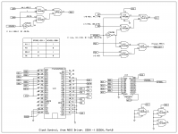
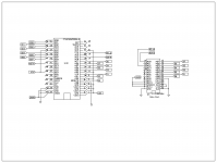
Attached Schematic, to control Clock from host.
In this case UM2232H is required, PortB controls the clock selector.
I found IDT 72V05 (3.3V) has less inventory than 7205, 7206.. (5V)
and precision Clocks on eBay are 5V driven.
This circuit uses 74HC, so easy to change whole voltage to 5V.
UM2232H is 5V tolerant. FYI.
In this case UM2232H is required, PortB controls the clock selector.
I found IDT 72V05 (3.3V) has less inventory than 7205, 7206.. (5V)
and precision Clocks on eBay are 5V driven.
This circuit uses 74HC, so easy to change whole voltage to 5V.
UM2232H is 5V tolerant. FYI.
Attachments
foobar is working now..
I had terrible mistake.
Before
After
kNumOutputs = 24
numChannels = 2
So, I wrote more than requested, then broke some memory in foobar.
Always doubt myself!
current source code is on my page.
I had terrible mistake.
Before
Code:
	for (i = 0; i < kNumOutputs; i++, info++)
	{
		internalBuffers[i] = (unsigned char *)malloc(blockFrames * 3 * 2);
		memset(internalBuffers[i], 0, blockFrames * 3 * 2);
		info->buffers[0] = internalBuffers[i];
		info->buffers[1] = internalBuffers[i] + blockFrames * 3;
	}
Code:
	for (i = 0; i < kNumOutputs; i++)
	{
		internalBuffers[i] = new unsigned char[blockFrames * 3 * 2];
		for (int j = 0 ; j < blockFrames * 3 * 2; j++)
		{
			internalBuffers[i][j] = 0x00;
		}
	}
	for (i = 0; i < numChannels; i++, info++)
	{
		info->buffers[0] = internalBuffers[i];
		info->buffers[1] = internalBuffers[i] + blockFrames * 3;
		if (!info->isInput)	// output
		{
			outMap[activeOutputs] = info->channelNum;
		}
}numChannels = 2
So, I wrote more than requested, then broke some memory in foobar.
Always doubt myself!
current source code is on my page.
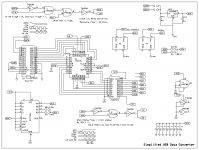
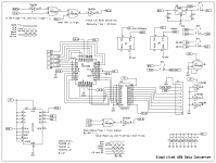
Here is simplified USB Digital converter, only usses FTDI + FIFO + DIP devices.
Parallel - Serial conversion is done in source code.
test program only uses Bit 0 (LRCK) and Bit 1 (Channel 1/2).
By this serialization (pick 1 bit from PCM data, and assign to send buffer)..
This byte stream can be sent to I2S directly.
This source code is only for functional test, under CPU load there is dropping.
To use this USB DDC, multi threaded ASIO driver should be required.
Parallel - Serial conversion is done in source code.
Code:
			//LRCK = 1, RH
			LRCK = 0x01;
			for (int k = 0; k < 8; k++) {
				ch12 = (RH>>(7-k))&0x01;
				*(pSend + j*64 + 33 + k) = LRCK | (ch12<<1);
}By this serialization (pick 1 bit from PCM data, and assign to send buffer)..
Code:
Bit 0:
0000000000000000000000000000000011111111111111111111111111111111
Bit 1:
0LLLLLLLLLLLLLLLL0000000000000000RRRRRRRRRRRRRRRR0000000000000000
This source code is only for functional test, under CPU load there is dropping.
To use this USB DDC, multi threaded ASIO driver should be required.
Attachments
Koon, good to see you still going with your experiments.
I've been waiting 3 weeks for my $15 Cypress development board to arrive, I suppose its the Christmas post slowdown but should be here for the Christmas vacation to complete my Cypress High Speed USB to multichannel I2S prototype (using async interrupt transfer mode).
Cypress CY7C68013A-56 EZ-USB FX2LP USB2.0 Develope Board Module GPIO Pin For DIY | eBay
Multi-threaded ASIO driver may help reduce dropped samples, but you may also want to increase the size of your FIFO (at the expense of latency delays) or reduce the sample rate. I don't think this design would work so well with 384K sampling, personally I won't be using my prototype higher than 192KHz.
Also, what software do you use for your schematic drawings?
- Home
- Source & Line
- Digital Line Level
- 24 channels USB to I2S interface (with Source codes, ASIO/VHDL/Schematic)