We've now also checked the PSRR of the output to V2 and V3 of the bipolar circuit.
It's about -80dB, pretty independent of noise frequency.
Not as bad as I thought. But still needs attention (separate, regulated, low noise supplies from V1).
Too complicated for not much gain, plus the need for tight hfe match.
We'll stick to JFETs for simplicity, at least for now.
Patrick
It's about -80dB, pretty independent of noise frequency.
Not as bad as I thought. But still needs attention (separate, regulated, low noise supplies from V1).
Too complicated for not much gain, plus the need for tight hfe match.
We'll stick to JFETs for simplicity, at least for now.
Patrick
Hi,
 first post vanished in the Off of internet universe
Did the sims again with the different models You supplied.
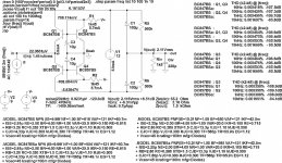
Find the results in the attached files. Even with the variations in the BF-values of the models the THD remains extremely low. Under no circumstances could I get Your numbers. asc.file included to allow for own sims and verification.
The leakage (base current) reduces the current through Riv -and the output voltage- only by a miniscule fraction (here: 0.3%). This is much smaller as the change to the next higher Riv-value even in the E96 series.
Matching of the transistors is most definitely needed with JFETs while the matching of bipolar Duals is usually quite good and NXP, Infineon and other manufacturers offer matched Dual versions quite cheap.
Regarding current mirror action, this only takes place dc-wise. Inputs to the CMs are Q3s and Q4s collectors (in my attched schematic), outputs are Q1s and Q2s collectors. AC-signal-wise the input is the common emitters of Q1 and Q2, the outputs the collectors of Q1 and Q2, hence complementary common base stages. Q3 and Q4 then just make up a part of the biasing network, which could also be made from a chain of resistors, or with diodes, as in M.Leach´s common base circuit. The advantage of using the same transistors -diode connected- for Q1/Q3 and Q2/Q4 is good temperature compensation.
Of course does the biasing network mean a greater part number count against the JFET-Version, but those few extra parts may be small sized and very cheap. The additional supplies are not necessarily needed as M.Leachs circuit demonstrates. But a buffer stage will very probabely be needed anyway. This buffer cannot be powered by V1 but needs its own supply. So why not use those supplies (v2 and V3) for biasing purposes and ´divide´ the biasing from signal-path. One could maybe use a switcher circuit like LTs LT1533 to generate V1 from one or both V2,V3.
As I see it the main differences between the JFET and bipolar versions are:
- sourceability and cost: It is more difficult to source matched N-N or even matched P-P JFETs. Parameter variation off of the shelf is much better with bipolars. Number of useable parts, availability of complementary and matched Dual parts and cost of those parts speaks for bipolar. Prices for matched Dual bipolars are lower than those for the JFETs. Not to talk about the risk of purchasing fake devices.
- current and voltage demands are lower with bipolars, which allows for usage of compact SMD-casings.
- ~one order lower input impedance (and seemingly more constant up into the MHz range) of the bipolar stage. Depending on the DAC-chip used this may be an issue.
- lower current and voltage demands of bipolars allow for compact SMD casings
jauu
Calvin
ps: basically I favour JFETs, because they allow for etremely simple circuits and they can sound fantastic. It´s just a pity that it is becoming increasingly difficult or expensive to source good parts and that matching or screening is nearly always needed. So the suggestion for bipolars is just meant as an alternative.
first post vanished in the Off of internet universe Did the sims again with the different models You supplied.
Find the results in the attached files. Even with the variations in the BF-values of the models the THD remains extremely low. Under no circumstances could I get Your numbers. asc.file included to allow for own sims and verification.
The leakage (base current) reduces the current through Riv -and the output voltage- only by a miniscule fraction (here: 0.3%). This is much smaller as the change to the next higher Riv-value even in the E96 series.
Matching of the transistors is most definitely needed with JFETs while the matching of bipolar Duals is usually quite good and NXP, Infineon and other manufacturers offer matched Dual versions quite cheap.
Regarding current mirror action, this only takes place dc-wise. Inputs to the CMs are Q3s and Q4s collectors (in my attched schematic), outputs are Q1s and Q2s collectors. AC-signal-wise the input is the common emitters of Q1 and Q2, the outputs the collectors of Q1 and Q2, hence complementary common base stages. Q3 and Q4 then just make up a part of the biasing network, which could also be made from a chain of resistors, or with diodes, as in M.Leach´s common base circuit. The advantage of using the same transistors -diode connected- for Q1/Q3 and Q2/Q4 is good temperature compensation.
Of course does the biasing network mean a greater part number count against the JFET-Version, but those few extra parts may be small sized and very cheap. The additional supplies are not necessarily needed as M.Leachs circuit demonstrates. But a buffer stage will very probabely be needed anyway. This buffer cannot be powered by V1 but needs its own supply. So why not use those supplies (v2 and V3) for biasing purposes and ´divide´ the biasing from signal-path. One could maybe use a switcher circuit like LTs LT1533 to generate V1 from one or both V2,V3.
As I see it the main differences between the JFET and bipolar versions are:
- sourceability and cost: It is more difficult to source matched N-N or even matched P-P JFETs. Parameter variation off of the shelf is much better with bipolars. Number of useable parts, availability of complementary and matched Dual parts and cost of those parts speaks for bipolar. Prices for matched Dual bipolars are lower than those for the JFETs. Not to talk about the risk of purchasing fake devices.
- current and voltage demands are lower with bipolars, which allows for usage of compact SMD-casings.
- ~one order lower input impedance (and seemingly more constant up into the MHz range) of the bipolar stage. Depending on the DAC-chip used this may be an issue.
- lower current and voltage demands of bipolars allow for compact SMD casings
jauu
Calvin
ps: basically I favour JFETs, because they allow for etremely simple circuits and they can sound fantastic. It´s just a pity that it is becoming increasingly difficult or expensive to source good parts and that matching or screening is nearly always needed. So the suggestion for bipolars is just meant as an alternative.
Attachments
Last edited:
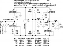
In the CEN IV, you only need to match Idss of the 2 JFETs.
In the SEN IV, only the sum of Idss of the top & bottom pairs needs to match.
So no difficult task.
There are still plenty of JFETs around for very reasonable prices, especially the N-FETs.
BJTs maybe cheaper (but not the matched pairs like MAT12), but not cheap enough to compensate for the expense of two additional supplies.
I like JFETs, because they are quadratic / polynomial and not exponential devices.
But of course I should be most interested in any experimental results that you might have with BJTs.
Regards,
Patrick
Yes, in the SEN circuit (only).
For example, the top 2 FETs can be 6mA and 7mA, and the bottom two can be 5mA & 8mA.
The sum for both pairs are then 13mA.
Of course a better match then this example makes sure the dissipation are more equal, and hence also the thermal tracking.
Patrick
For example, the top 2 FETs can be 6mA and 7mA, and the bottom two can be 5mA & 8mA.
The sum for both pairs are then 13mA.
Of course a better match then this example makes sure the dissipation are more equal, and hence also the thermal tracking.
Patrick
SEN has in simulation lower distortion.
Because you have paralleled FETs, they also have a bit less noise.
The rest is matter of taste.
The quad heatsink we call type 10.
They are included in the evaluation kit (see post #7).
For those who cannot find 2SJ74, you can try here :
http://www.diyaudio.com/forums/swap-meet/131284-toshiba-2sk170bl-sales-12.html#post2667790
I shall also make 40 pairs available at costs for evaluation kit subscribers.
Patrick
Hi,
Patrick, I may repeat myself but...You don´t need the extra power supplies V2, V3 for the bipolar IV-stage. A biasing network similar to that of M.Leachs common base stage is fully sufficient and You get away with a single floating supply just as with the JFET-stage.
Since the gain and the bandwidth of the IV-stage depend on the input impedance of a following device, a buffer-stage between IV-stage and the following device is more than only an option.
If You decide to add a buffer-stage -and regardless of the use of JFET or bipolar transistors- You need extra supplies, because You can´t use the floating supply of the IV-stage as supply for the buffer-stage at the same.
In this case You may use the power supplies of the buffer stage to bias the IV-stage, thereby ´parting´ signal current path and bias path. The ´increased´ complexity of the buffered bipolar-stage against a buffered JFET-stage reduces to a few biasing network parts only.
Matched transistor pairs of same polarity come in form of the BCM847/857 of NXP, costing 0.43/0.44€ per pcs at Digikey.
Matched Duals with opposite polarity come in form of the BC847BPN from NXP for 0.54€. As the simulation showed, differences in hfe (BF-value) had no major influence on THD-figures. So all three devices should be useable as off of the shelf, without the harassment or cost of matching. Paralleling same-polarity devices as in the SEN increased THD in the sims by orders more and doesn´t seem to be a good option.
So if someone has difficulties in sourcing matched JFETs, or doesn´t want to spend the time and effort of matching, but still likes these simple circuits, the bipolar version may be an alternative worth thinking of...no more, no less.
jauu
Calvin
Calvin,
I try my best to avoid getting an open discussion into a contest.
BCM847 has a noise figure of 3dB, and hfe match of 10%
http://www.nxp.com/documents/data_sheet/BCM847BV_BS_DS.pdf
SSM2212 on the other hand has a noise figure of 1nV.sqrt(Hz), and hfe match of 5% guaranteed, 0.5% typical.
http://www.analog.com/static/imported-files/data_sheets/SSM2212.pdf
They cost over 6€ a piece. Metal cased MAT12 costs quite a bit more.
I know you can supply V2, V3 from V1. But V1 is floating and swing with the output signal.
I do not consider a potential divider and a cap to be good enough as supply for V2, V3, when V1 can have a ripple of 2Vrms relative to Gnd.
Personal choices, I admit.
I think you would agree that in its simplest form, the bipolar version still has a lot more components than the JFET version.
And as I said, I do not like exponential devices. My prejudice.
Patrick
PS My preamp has small signal JFET inputs, so I do not intend to add a buffer after R_iv.
.
Last edited:
Very clever Joachim.
Essentially a SEN IV frontend (CEN also possible) but with cascode.
Then uses 2 cascoded current mirror to reflect the signal current directly into the R_iv (or RIAA filter network).
The current mirrors are hanging on the rails and hence no connection to Gnd.
They essentially do the same job as the "coupling" caps.
So the extra complication is justified.
The output buffer is probably necessary for RIAA.
If I am not wrong, one can also do current mirror with FETs, with all the matching headaches.
Patrick
Hi,
V2 and V3 are independant and optional supplies. They are not generated from the floating supply V1. Instead V1 might be generated from V2 and V3 via a switcher-IC like the LT1533.
As the sim showed even variations of 5% in hfe didn´t increase THD considerably. The BCs are specced with a maximum deviation of 0.9 and a Vbe-difference of 2mV. Taken from a batch the variations are generally lower. Until a test setup prooves different I take the sim for believable.
Working in the current domain noise voltage figures are of minor importance and there is no need for dedicated low voltage noise devices.
Simulation with the 2N4401/4403, which are well known as performing very lownoise in phono MC-stages, showed higher noise figures.
Running the BCs in a current range of 2-10mA results in low noise figures, high bandwidth and good THD-behaviour (a nice falling spectrum with increasing order of K). From simulation results one would not be able to blind judge between JFET and bipolar.
And You´re right Patrick...this should not become a contest.
I just wanted to show an alternative solution for those who may have difficulties in sourcing or matching JFETs. But the cons You named mostly don´t apply or do apply for the JFET circuit also. The only worth to mention differences between JFET and bipolar circuit are the need for matching JFETs and the additional parts to bias the bipolars.
Joachim is basically right about the functioning of the buffer with the floating supply. But he´s right only half. The problem is, that the signal current divides between the I/V-stage and the Buffer-stage!
This has a serious drawback. The output voltage now depends on the value of the load impedance at the Buffer-output again and takes on the value of Isignal(dac) x Riv||Rload.
The buffer basically looses its main functionality, which is to isolate the IV-stage and to make the parameters of the IV-stage independant of the following load impedance. It even looses the function to supply higher currents than Isignal(dac)-I(Riv) to the load. Even though V1 is a voltage source (constant voltage, unlimited current supply), the buffered stages output current is limited to approximately the DAC-signal current.
This are the reasons why the Buffer-stage should have its own independant power supplies.
"The Starless and Bible Black MC RIAA" reminds me of a topology named Satri which also worked with current mirrors. The doubled CMs are used in integrated circuits, but need very careful matching when built with discrete parts or oscillation occurs.
jauu
Calvin
For the 4th timeI know you can supply V2, V3 from V1.
V2 and V3 are independant and optional supplies. They are not generated from the floating supply V1. Instead V1 might be generated from V2 and V3 via a switcher-IC like the LT1533.
As the sim showed even variations of 5% in hfe didn´t increase THD considerably. The BCs are specced with a maximum deviation of 0.9 and a Vbe-difference of 2mV. Taken from a batch the variations are generally lower. Until a test setup prooves different I take the sim for believable.
Working in the current domain noise voltage figures are of minor importance and there is no need for dedicated low voltage noise devices.
Simulation with the 2N4401/4403, which are well known as performing very lownoise in phono MC-stages, showed higher noise figures.
Running the BCs in a current range of 2-10mA results in low noise figures, high bandwidth and good THD-behaviour (a nice falling spectrum with increasing order of K). From simulation results one would not be able to blind judge between JFET and bipolar.
And You´re right Patrick...this should not become a contest.
I just wanted to show an alternative solution for those who may have difficulties in sourcing or matching JFETs. But the cons You named mostly don´t apply or do apply for the JFET circuit also. The only worth to mention differences between JFET and bipolar circuit are the need for matching JFETs and the additional parts to bias the bipolars.
Joachim is basically right about the functioning of the buffer with the floating supply. But he´s right only half. The problem is, that the signal current divides between the I/V-stage and the Buffer-stage!
This has a serious drawback. The output voltage now depends on the value of the load impedance at the Buffer-output again and takes on the value of Isignal(dac) x Riv||Rload.
The buffer basically looses its main functionality, which is to isolate the IV-stage and to make the parameters of the IV-stage independant of the following load impedance. It even looses the function to supply higher currents than Isignal(dac)-I(Riv) to the load. Even though V1 is a voltage source (constant voltage, unlimited current supply), the buffered stages output current is limited to approximately the DAC-signal current.
This are the reasons why the Buffer-stage should have its own independant power supplies.
"The Starless and Bible Black MC RIAA" reminds me of a topology named Satri which also worked with current mirrors. The doubled CMs are used in integrated circuits, but need very careful matching when built with discrete parts or oscillation occurs.
jauu
Calvin
Attachments
Last edited:
If I understand correctly. Joachim's circuit uses the current mirror to fold the signal current back to R_iv. This is, in a way, similar to this circuit I posted a while ago using a MOSFET folded cascode (the idea came from John Cur"l's blowtorch thread) :
http://www.diyaudio.com/forums/pass-labs/173291-zen-i-v-converter.html#post2298531
The nice thing about the current mirror is that it hangs on the rails, and has no Gnd connection.
I have a feeling that it might even work with fixed rails. But I need to check a few things first beforehand.
If it works in Sims, we'll most likely give it a try, with a CEN frontend.
Patrick
Yes, a folded cascode works too. Instead of the drain resistors one can use a mirror as constant current source or a constant current source. That way you can get a tremendoes Gain-Bandwidth product. I have your SEN circuit ( slightly modified ) working as a pre-pre.
It sounds good and it is quiet. Yes, the CEN is something to try too.
It sounds good and it is quiet. Yes, the CEN is something to try too.
- Home
- Source & Line
- Digital Line Level
- Zen -> Cen -> Sen, evolution of a minimalistic IV Converter