Hey Ian, I think I'll receive the FIFO early next week (very excited!) but I have a couple of quick questions - Do I need to worry about termination resistors at my DAC for the I2S signal terminations?
My DAC has 2 x I2S inputs on its main board, via 5-pin JST connectors. I think only one of these connectors has 75 ohm termination resistors and the other does not. Photo below.
Also, I'll need to terminate the MCLK signal into the connector at the DAC - Do you see any issues with me cutting the 6" U.FL coaxial cable coax to the same length as the 4” double-ended PH 2.0 mm 7-pin I2S bridge cable and terminating it with a JST crimp lug?
Thanks Ian.
Hey Ian, I think I'll receive the FIFO early next week (very excited!) but I have a couple of quick questions - Do I need to worry about termination resistors at my DAC for the I2S signal terminations?
My DAC has 2 x I2S inputs on its main board, via 5-pin JST connectors. I think only one of these connectors has 75 ohm termination resistors and the other does not. Photo below.
Also, I'll need to terminate the MCLK signal into the connector at the DAC - Do you see any issues with me cutting the 6" U.FL coaxial cable coax to the same length as the 4” double-ended PH 2.0 mm 7-pin I2S bridge cable and terminating it with a JST crimp lug?
Thanks Ian.
View attachment 499830
Hi aive,
All signals from Ian FIFO KIT are already 50ohm source terminated. You don't need any termination resistor at your DAC input. Even for the MCLK signal. Please no worry at all.
After reviewing your picture, I don't think those 75ohm resistors have business with any of your I2S inputs.
Please keep in mind, don't share same signal with more than one input. Dual XO II has two groups of output. You should have enough to use.
Good weekend.
Ian
Would someone be so kind to check if capacitor connection shown at attachment is tied to ground? I installed a SMA connector and one leg soldered with near capacitor...
It looks to be ground, so I'd prefer not to remove tin, but I need to be 100% sure!
Hi fralippo,
Yes you are right, the terminal of that MLCC was grounded. So, no worry, just go ahead with it.
I got your email, I thought, but actually I forgot replying, I'm sorry
") .
.Good luck to your project.
Ian
Free Raspberry Pi I2S cap PCBs are ready, please send message with your address
Hi guys,
Free Raspberry Pi I2S cap adapter PCBs are now ready. I have 30 of them in total. I hope that will be enough. If more people want it, I’ll consider making more down the road.
1. If you just want the free Raspberry Pi I2S cap PCB, you only need to send a diyAudio message to me with your shipping address. You will soon receive the PCB in an envelope. The BOM and part numbers are all in the schematics I attached at end of this post.
2. If your want the free Raspberry Pi I2S cap PCB together with SMT connector package or something else, you also need to send me a diyAudio message by following an order form to iancanada.mail@gmail.com. I'll follow up with a PP invoice with the lowest possible shipping to suit you best (there will be no tracking number unless you need it). The order form can also be downloaded at end of this post.
I will create a list based on the order of when I get your message. It will be stopped once all PCBs are run out.
Please note there is a small mistake on the PCB silkscreen: label of 5V and GND were revised. Just label I promise.
I’m very happy to share this small toy with you all, have fun!
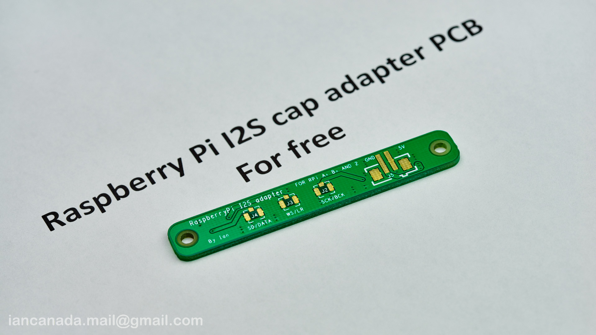
FreeRaspBerryPiI2Scap by Ian, on Flickr
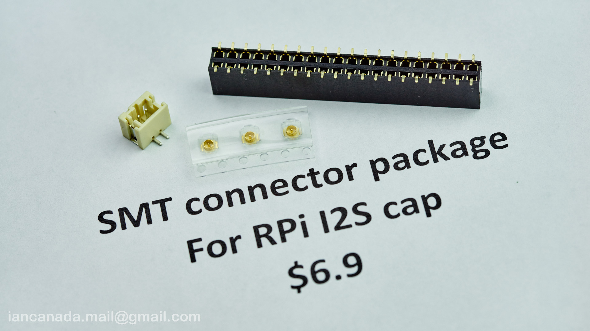
SMTconnectorPackage by Ian, on Flickr
Ian
Hi guys,
Free Raspberry Pi I2S cap adapter PCBs are now ready. I have 30 of them in total. I hope that will be enough. If more people want it, I’ll consider making more down the road.
1. If you just want the free Raspberry Pi I2S cap PCB, you only need to send a diyAudio message to me with your shipping address. You will soon receive the PCB in an envelope. The BOM and part numbers are all in the schematics I attached at end of this post.
2. If your want the free Raspberry Pi I2S cap PCB together with SMT connector package or something else, you also need to send me a diyAudio message by following an order form to iancanada.mail@gmail.com. I'll follow up with a PP invoice with the lowest possible shipping to suit you best (there will be no tracking number unless you need it). The order form can also be downloaded at end of this post.
I will create a list based on the order of when I get your message. It will be stopped once all PCBs are run out.
Please note there is a small mistake on the PCB silkscreen: label of 5V and GND were revised. Just label I promise
.I’m very happy to share this small toy with you all, have fun!
FreeRaspBerryPiI2Scap by Ian, on Flickr
SMTconnectorPackage by Ian, on Flickr
Ian
Attachments
Raspberry Pi I2S cap PCB shipping list so far
Please let me know if your sent PM but not on the list
1 wengtech
2 Zoef
3 clivem
4 marcus1
5 Greg Stewart
6 tubesguy
7 casshan
8 ccliu
9 aive
10 burninggecko
11 ernesternest
12 analog_sa
13 RollE2k
14 jacczy
15 oyvind
16 nedi
17 fordgtlover
18 Malvin
19 EHYeon
20 Pulsar Clock
21 MadKid
Ian
Please let me know if your sent PM but not on the list
1 wengtech
2 Zoef
3 clivem
4 marcus1
5 Greg Stewart
6 tubesguy
7 casshan
8 ccliu
9 aive
10 burninggecko
11 ernesternest
12 analog_sa
13 RollE2k
14 jacczy
15 oyvind
16 nedi
17 fordgtlover
18 Malvin
19 EHYeon
20 Pulsar Clock
21 MadKid
Ian
Hey guys, I am planning to run panasonic 18650 battery into the clock board. They are rated at 3.6-4.2v with a step up to 5v. Is it necessary to place battery management before the board? Or could someone explain the function of the board? I am still half way reading the thread and the search function is stormed by the ordering list. Would expect a quicker answer asking here as I am new in diy stuff. Thanks a lot.
Hey guys, I am planning to run panasonic 18650 battery into the clock board. They are rated at 3.6-4.2v with a step up to 5v. Is it necessary to place battery management before the board? Or could someone explain the function of the board? I am still half way reading the thread and the search function is stormed by the ordering list. Would expect a quicker answer asking here as I am new in diy stuff. Thanks a lot.
I would like to recommend 18650 LifePO4 battery for Dual XO II, which the voltage will be between 3.2-3.4V, so you can just short the reg by a jumper, no reg will be needed.
Ian
Raspberry Pi I2S cap PCB shipping list so far
1 wengtech
2 Zoef
3 clivem
4 marcus1
5 Greg Stewart
6 tubesguy
7 casshan
8 ccliu
9 aive
10 burninggecko*
11 ernesternest
12 analog_sa
13 RollE2k
14 jacczy
15 oyvind
16 nedi
17 fordgtlover
18 Malvin
19 EHYeon
20 Pulsar Clock
21 MadKid
22 number9
23 KVL
24 flowerpot
25 spm
26 ed linssen
27 supra
28 ppap64
Thank you for your interest
Ian
I would like to recommend 18650 LifePO4 battery for Dual XO II, which the voltage will be between 3.2-3.4V, so you can just short the reg by a jumper, no reg will be needed.
Ian
Thanks for the suggestion. I have a doubt with the spdif interface. Since the isolator board is placed, I should power the interface with separate power supply and disconnect all the connections to the FIFO kit. Or perhabs, I need another isolator?
- Home
- Source & Line
- Digital Line Level
- Asynchronous I2S FIFO project, an ultimate weapon to fight the jitter