fridrik, i'm not sure these regulators are that suitable for an IV stage, LDOs in priciple and across the board generally rely heavily on their output capacitors to provide for transient current demands ie. their transient response is directly proportional to the output capacitance; by themselves while the noise is good and low, the transient response is usually pretty ordinary.
this is fine for things that have low, or stable current demands that can be supplied by lowZ decoupling at point of load, but IV stages though not having huge current demand (most of them), do have transient current demands that may be enough to deplete local decoupling.
what do you think Ian?
Thanks for your comment qups. I will take this in consideration, But be aware that I'm trying to remplace a LM337T-ND of the original design which is also supposed to be some kind of LDO ;-)
For the moment I will just use the TPS7A4700 to power the FIFO and the SPDIF adapter. Ian do you suggest 2 LDO board to power Fifo+SPDIF ?
TPS7A4700 PCB run out
I'm afraid I run out all of the TPS7A4700 PCB. Thank you so much for your very kind donations. I appreciate!
Will combine the shipment for those who has a GBIII order number. PCB shipped today to all of those without a GBIII order number.
Pretty sure I'll supply this PCB again with the Si570 board.
Thanks again
My best regards.
Ian
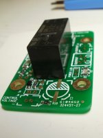
Forgot to mention passive battery management board has been tested and works great in standard configuration. Thanks Ian!
Hi TheShaman,
Good to know that, you did great job! board looks nice, good picture
") .
. Please let me know if you need any support.
Ian
fridrik, i'm not sure these regulators are that suitable for an IV stage, LDOs in priciple and across the board generally rely heavily on their output capacitors to provide for transient current demands ie. their transient response is directly proportional to the output capacitance; by themselves while the noise is good and low, the transient response is usually pretty ordinary.
this is fine for things that have low, or stable current demands that can be supplied by lowZ decoupling at point of load, but IV stages though not having huge current demand (most of them), do have transient current demands that may be enough to deplete local decoupling.
what do you think Ian?
Although 4700 has very low noise density, but it optimized to VCO/XO/RF power supply with very good high frequency performance and can drive low ESR MLCC output capacitors. I still think a well designed shunt reg is better for a I/V. But I might be wrong. Hope somebody can give 4700 a try for analog applications.
Ian
if you look at te step response it confirms what i'm saying and the psrr could be better too (-60 -70dB through the audio frequency range), better than any other LDO i've seen however. its perfectly suitable for how you are using it Ian, it has amazingly low noise, but its not really the thing supplying the load current in your designs, its supplying the capacitors which are supplying the load, so the caps are/should be chosen with this in mind
have you exposed the sense pin on your PCB Ian? or have you just tied it to the output voltage?
nvm i'll look at your schematic....
have you exposed the sense pin on your PCB Ian? or have you just tied it to the output voltage?
nvm i'll look at your schematic....
Last edited:
if you look at te step response it confirms what i'm saying and the psrr could be better too (-60 -70dB through the audio frequency range), better than any other LDO i've seen however. its perfectly suitable for how you are using it Ian, it has amazingly low noise, but its not really the thing supplying the load current in your designs, its supplying the capacitors which are supplying the load, so the caps are/should be chosen with this in mind
have you exposed the sense pin on your PCB Ian? or have you just tied it to the output voltage?
Agree. I have been trying different caps for it in the past weeks. It seems MLCC plays batter then TAN, through it's more sensitive to mechanical vibration. But which MLCC is the best? I'm still wondering and looking for.
Of course, the sense line should always be independent from the output
Regards,
Ian
Last edited:
many designs, particularly if the reg is on the same board just tie it directly to the output to save trouble and assuming that there will not be significant voltage drop over a short trace, but external designs like yours that can and will have unknown loads its better to have it available, so glad you did also its pretty unique in that most adjustable regulators do not have a sense pin, because the pin that is usually used for sense is changed for an ADJ pin, sensing the voltage across the setting resistors. As a result its often only fixed voltage LDOs that have a sense pin.
as for Caps, I would use a mix of Panasonic SP-CAP (SX variant) (I use these whenever I can, Acko uses them too, great caps) and MLCC and I mightve looked at using some AVX Accu-P thin film caps for the HF Si570 decoupling directly on the pins
also its pretty unique in that most adjustable regulators do not have a sense pin, because the pin that is usually used for sense is changed for an ADJ pin, sensing the voltage across the setting resistors. As a result its often only fixed voltage LDOs that have a sense pin.as for Caps, I would use a mix of Panasonic SP-CAP (SX variant) (I use these whenever I can, Acko uses them too, great caps) and MLCC and I mightve looked at using some AVX Accu-P thin film caps for the HF Si570 decoupling directly on the pins
I've been wondering if one of those tiny cap arrays would be useful for Si570 decoupling ...
DK - 490-3446-1-ND (only rated for 6.3V) - GNM314R70J105MA01L Murata Electronics North America | 490-3446-1-ND | DigiKey
Some datasheets - http://search.murata.co.jp/Ceramy/image/img/PDF/ENG/GNM314R70J105MA01.pdf
http://www.mouser.com/catalog/specsheets/Murata GNM Series.pdf
An AVX version - http://www.avx.com/docs/Catalogs/w2lw3l.pdf
many designs, particularly if the reg is on the same board just tie it directly to the output to save trouble and assuming that there will not be significant voltage drop over a short trace, but external designs like yours that can and will have unknown loads its better to have it available, so glad you did
as for Caps, I would use a mix of Panasonic SP-CAP (SX variant) (I use these whenever I can, Acko uses them too, great caps) and MLCC and I mightve looked at using some AVX Accu-P thin film caps for the HF Si570 decoupling directly on the pins
I've been wondering if one of those tiny cap arrays would be useful for Si570 decoupling ...
DK - 490-3446-1-ND (only rated for 6.3V) - GNM314R70J105MA01L Murata Electronics North America | 490-3446-1-ND | DigiKey
Some datasheets - http://search.murata.co.jp/Ceramy/image/img/PDF/ENG/GNM314R70J105MA01.pdf
http://www.mouser.com/catalog/specsheets/Murata GNM Series.pdf
An AVX version - http://www.avx.com/docs/Catalogs/w2lw3l.pdf
Good ideas. Based on my testing result, capacitors are very very important for a clock power supply.
Ian
the thin film caps are pretty much the most linear cap you can find, unfortunately not available in large values, but for close HF decoupling on the Si570 they should be perfect. hopefully one day they will make them in larger 10-100nF sizes.
are you also playing with building planar capacitance into the PCB design itself?
is the pattern on the tps regulator board 7343 size? I have used the tantalum/polymer caps you have tried (the orange ones) and much prefer the SP-CAP, as you see in the part I linked, ripple rejection is very good and 5-7mOhms impedance for a ~100µF cap is pretty excellent.
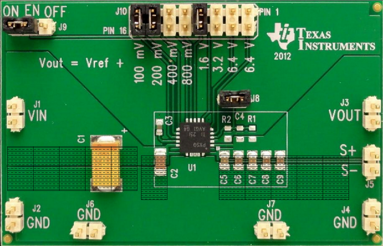
I'm aiming to use the tps7a4700 evalboard in a project and is looking to replace the X5R caps with Panasonic SP's.
After some handywork this is what should be the available space if mounted next to each other but most likely there will be some spacing.
Not shure that this is the right thread for this but since there is disscusion about both the caps and the reulator so........
For C1 and C5-9 there will be panasonic sp caps. I'm not shure about C2, suggestions anyone ? Probably another sp I think.
This comes from the user guide:
Nothing said about input capasitance values, there is 47+10uf mounted now.
Is there any reason to increase on that ?
After some handywork this is what should be the available space if mounted next to each other but most likely there will be some spacing.
Not shure that this is the right thread for this but since there is disscusion about both the caps and the reulator so........
For C1 and C5-9 there will be panasonic sp caps. I'm not shure about C2, suggestions anyone ? Probably another sp I think.
This comes from the user guide:
The TPS7A4700 is designed and characterized for operation with ceramic capacitors of 10 μF or greater at the
input and output. Optimal noise performance is characterized using a total output capacitor value of 50 μF
Nothing said about input capasitance values, there is 47+10uf mounted now.
Is there any reason to increase on that ?
no its not the correct thread for discussion of the regulator on the demo board to power a completely different DSP/DAC to what is under discussion here.... which is not even a dac, nor is the board under discussion the regulator demo board
I must admit to being confused with your use of this regulator after a raw supply and before placid shunt regs, did you not buy the correct voltage power transformer? adding all this extra caps for low impedance storage when you are following with a shunt reg makes no sense to me; it seems like you are replacing proper measurement and design with overkill
I must admit to being confused with your use of this regulator after a raw supply and before placid shunt regs, did you not buy the correct voltage power transformer? adding all this extra caps for low impedance storage when you are following with a shunt reg makes no sense to me; it seems like you are replacing proper measurement and design with overkill
Last edited:
It's in the pdf documentation for the eval board on page 2
NOTE: The positive input lead and ground return lead from the input power supply should be twisted
and kept as short as possible to minimize EMI and source inductance. Additional bulk
capacitance in the form of a Tantalum cap (47 µF; 35 V) has been added to the EVM at C1
to counter source inductances that may cause ringing on the load transient waveform during
higher current transients. This bulk capacitance should not be necessary in a typical
application circuit.
no its not the correct thread for discussion of the regulator on the demo board to power a completely different DSP/DAC to what is under discussion here.... which is not even a dac, nor is the board under discussion the regulator demo board
I must admit to being confused with your use of this regulator after a raw supply and before placid shunt regs, did you not buy the correct voltage power transformer? adding all this extra caps for low impedance storage when you are following with a shunt reg makes no sense to me; it seems like you are replacing proper measurement and design with overkill
Point taken, I'll start a thread for this specific project. You're welcome when posted.
- Home
- Source & Line
- Digital Line Level
- Asynchronous I2S FIFO project, an ultimate weapon to fight the jitter