The Si570 based clock board is working now
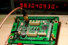
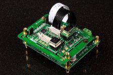
The prototype of Si570 based clock board is working now. It’s generating the frequencies I want. For DAC applications, now it could be 11.2896, 12.2880, 22.5792, 24.5760, 45.1584, 49.1520, 90.3168 and 98.3040 MHz.
At high frequency mode which designed especially for ESS9018, the output frequency will be fixed at 90.3168 and 98.3040 MHz. The *Fs range will be from 256*Fs to 2048*Fs corresponding to 44.1Khz to 384KHz.
At low frequency mode for classical DAC, the MCLK will be changed automatically from 11.2896 to 49.1520 MHZ corresponding to 44.1KHz to 192KHz with *Fs fixed at 256*Fs.
The next step, I’ll run this Si570 based FIFO KIT with ESS9018 BIII at sync mode on 90.3168 and 98.3040 MHz.
Ian
Attachments
Last edited:
Any possible to stack the clock board on top of the FIFO board?
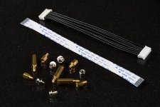
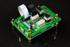
The FIFO KIT wasn’t designed this way originally. But to stack the clock board on top of the FIFO board will save a great deal of space, especially for a small DAC case. So, I was wondering is there any possible?
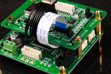
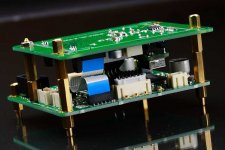
I realized both FIFO board and the clock board have same pitch of mounting holes on vertical side. So I ordered some 6” FPC/FFC cables. I did a try today, the answer now is YES! It looks just nice. Two standoffs assembled throughout the base feet. Another standoff could be a support for there is no mound hole underneath. The last mounting hole on the clock board has to be left open. Some components right over there.
I don’t think a 6” FPC/FFC cable gonna be any problem for the clock signal. But I have to confirm, at least for high Fs applications such as 384 KHz.
Ian
The FIFO KIT wasn’t designed this way originally. But to stack the clock board on top of the FIFO board will save a great deal of space, especially for a small DAC case. So, I was wondering is there any possible?
I realized both FIFO board and the clock board have same pitch of mounting holes on vertical side. So I ordered some 6” FPC/FFC cables. I did a try today, the answer now is YES! It looks just nice. Two standoffs assembled throughout the base feet. Another standoff could be a support for there is no mound hole underneath. The last mounting hole on the clock board has to be left open. Some components right over there.
I don’t think a 6” FPC/FFC cable gonna be any problem for the clock signal. But I have to confirm, at least for high Fs applications such as 384 KHz.
Ian
Attachments
The FIFO KIT wasn’t designed this way originally. But to stack the clock board on top of the FIFO board will save a great deal of space, especially for a small DAC case. So, I was wondering is there any possible?
I realized both FIFO board and the clock board have same pitch of mounting holes on vertical side. So I ordered some 6” FPC/FFC cables. I did a try today, the answer now is YES! It looks just nice. Two standoffs assembled throughout the base feet. Another standoff could be a support for there is no mound hole underneath. The last mounting hole on the clock board has to be left open. Some components right over there.
I don’t think a 6” FPC/FFC cable gonna be any problem for the clock signal. But I have to confirm, at least for high Fs applications such as 384 KHz.
Ian
Ian
I am doing the same thing too, I've ordered the longer FPC/FFC cable and PH2.0 jumper a couple days ago

Ian
I am doing the same thing too, I've ordered the longer FPC/FFC cable and PH2.0 jumper a couple days ago
That's great. Compare with BIII, the FIFO KIT looks a bit bigger. And now, they match
.Regards,
Ian
The prototype of Si570 based clock board is working now. It’s generating the frequencies I want. For DAC applications, now it could be 11.2896, 12.2880, 22.5792, 24.5760, 45.1584, 49.1520, 90.3168 and 98.3040 MHz.
At high frequency mode which designed especially for ESS9018, the output frequency will be fixed at 90.3168 and 98.3040 MHz. The *Fs range will be from 256*Fs to 2048*Fs corresponding to 44.1Khz to 384KHz.
At low frequency mode for classical DAC, the MCLK will be changed automatically from 11.2896 to 49.1520 MHZ corresponding to 44.1KHz to 192KHz with *Fs fixed at 256*Fs.
The next step, I’ll run this Si570 based FIFO KIT with ESS9018 BIII at sync mode on 90.3168 and 98.3040 MHz.
Ian
Ian
Remember to have more output for Dual Mono or multi-channel
Universal SMT XO adapter
"Two optional 100n 0603 and one 1u 0805 MLCC are recommended. But if the XO has good internal decoupling capacitors, then you don’t need any of them."
PN: 445-1316-2-ND, 490-4785-1-ND
Ian
Does the CCHD-957 has good internal decoupling capacitors, I mean do I need to assemble the optional MLCC at the SMT XO adapter with this Crystek XO?
Andrey
Does the CCHD-957 has good internal decoupling capacitors, I mean do I need to assemble the optional MLCC at the SMT XO adapter with this Crystek XO?
Andrey
Yes, it does. You don't need the MLCC for CCHD-957.
Regards,
Ian
Ian
Remember to have more output for Dual Mono or multi-channel
Thanks bigpandahk, will do it later on. I may have some solutions even for now
.Regards,
Ian
...
I don’t think a 6” FPC/FFC cable gonna be any problem for the clock signal. But I have to confirm, at least for high Fs applications such as 384 KHz.
Ian
You can flip the clock board and use 1" cables, but it will look UGLY
You can flip the clock board and use 1" cables, but it will look UGLY
That's really a smart idea
. I did't think of it .Ian
May I ask two questions regarding an application of this great FIFO board to ES9018 DACs?
How many users are using a synchronous master clock method and how do they feel about the resulting sound quality?
In the case of usual asynchronous clocking, which top notch have they attained on DPLL bandwidth parameter for 192kHz/24bit I2S input? In general, they say the value can be an index to measure a jitter in incoming signals.
Thank you!
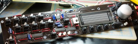
Stack clock board on top of FIFO board, an alternative solution from glt
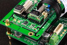
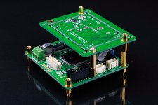
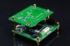
Another smart idea indeed. They look nice too. The good thing is the original short cables are OK for this solution. Just need longer standoffs. All connectors are at back of the PCB. But I don’t think it’s a big issue for a well settled system.
Ian
You can flip the clock board and use 1" cables, but it will look UGLY
Another smart idea indeed. They look nice too. The good thing is the original short cables are OK for this solution. Just need longer standoffs. All connectors are at back of the PCB. But I don’t think it’s a big issue for a well settled system.
Ian
Attachments
Another smart idea indeed. They look nice too. The good thing is the original short cables are OK for this solution. Just need longer standoffs. All connectors are at back of the PCB. But I don’t think it’s a big issue for a well settled system.
Ian
Yeah looks nice. You've designed your boards so they look nice on the backside too.
Ian,
my package arrived while I was traveling. I had last night time for a first time to admire the beauty of it. This is really awesome product, one of the best on DIY. I have to say you did a lot, from design, to assembly, and even packaging is professional. Actually, the whole product is groundbreaking and in its concept waaaay ahead of many consumer products. Thank you very much for putting so much effort for us! I hope you keep interest in developing and making available your products for us. Although it is convenient to receive the finished assembled board, many of us are capable of putting it together on our own. Please keep that in your mind if you will find that helpful.
Greatly thankful and happy new FIFO owner.
Ian,
my package arrived while I was traveling. I had last night time for a first time to admire the beauty of it. This is really awesome product, one of the best on DIY. I have to say you did a lot, from design, to assembly, and even packaging is professional. Actually, the whole product is groundbreaking and in its concept waaaay ahead of many consumer products. Thank you very much for putting so much effort for us! I hope you keep interest in developing and making available your products for us. Although it is convenient to receive the finished assembled board, many of us are capable of putting it together on our own. Please keep that in your mind if you will find that helpful.
Greatly thankful and happy new FIFO owner.
Thank you so much AR2. My pleasure. Enjoy having the FIFO with your system and let know any discovery on different XO and PSU.
Have a nice weekend.
Ian
May I ask two questions regarding an application of this great FIFO board to ES9018 DACs?
How many users are using a synchronous master clock method and how do they feel about the resulting sound quality?
In the case of usual asynchronous clocking, which top notch have they attained on DPLL bandwidth parameter for 192kHz/24bit I2S input? In general, they say the value can be an index to measure a jitter in incoming signals.
Thank you!
That number is only referenced to 9018 mclk, indicating some relationship between phase difference accumulating.
Will post some result once I'm done.
Ian
Ian, before I get my hands busy, a few questions if my understanding is correct. My configuration: Lightharmonic USB to I2S board, ES9012 DAC, FIFO board with S/PDIF board and dual clock.
1. If S/PDIF board is used, does using I2S signal from my USB board, is possible only through additional I2S input port on S/PDIF board?
2. My assumption is that DAC would work the best if used in synchronous mode with FIFO? My USB board also allows to be used as slave ( in master mode uses two clocks with automatic switching) Is it possible to send clock signals to both DAC and USB board? For slave mode I would need to send both clock signals? Or I would be better to leave USB board and just to sync DAC?
3. If I am to use front panel mounted input switching, do I replace your switch with any momentary switch? I need to allow for switching between two sources - S/PDIF and I2S from the board. I will not be sending any S/PDIF signal out.
4. What are the specs for LEDs or your board if I am to replace them with front panel mounted LEDs? I am thinking of taking off LEDs from the board and run wires to the front panel mounted LEDs for input markings.
5. Lastly, I am thinking of buying clocks in the following speeds for the dual clock board - 45.1584 MHz and 49.152 MHz, are these OK for ESS 9012? I am aware that FIFO board doesn't cover 384 KHz, but it goes up to 192KHz.
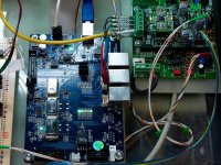
Here are few images of USB board and front panel board that already has switches and LEDs, that I would like to utilize. That board was preexisting and I am able to utilize it withs some modifications. That is explanation for questions No. 4.
Thank you
Vladimir
1. If S/PDIF board is used, does using I2S signal from my USB board, is possible only through additional I2S input port on S/PDIF board?
2. My assumption is that DAC would work the best if used in synchronous mode with FIFO? My USB board also allows to be used as slave ( in master mode uses two clocks with automatic switching) Is it possible to send clock signals to both DAC and USB board? For slave mode I would need to send both clock signals? Or I would be better to leave USB board and just to sync DAC?
3. If I am to use front panel mounted input switching, do I replace your switch with any momentary switch? I need to allow for switching between two sources - S/PDIF and I2S from the board. I will not be sending any S/PDIF signal out.
4. What are the specs for LEDs or your board if I am to replace them with front panel mounted LEDs? I am thinking of taking off LEDs from the board and run wires to the front panel mounted LEDs for input markings.
5. Lastly, I am thinking of buying clocks in the following speeds for the dual clock board - 45.1584 MHz and 49.152 MHz, are these OK for ESS 9012? I am aware that FIFO board doesn't cover 384 KHz, but it goes up to 192KHz.
Here are few images of USB board and front panel board that already has switches and LEDs, that I would like to utilize. That board was preexisting and I am able to utilize it withs some modifications. That is explanation for questions No. 4.
Thank you
Vladimir
Attachments
Last edited:
- Home
- Source & Line
- Digital Line Level
- Asynchronous I2S FIFO project, an ultimate weapon to fight the jitter