AR2, Finally got a change to look at all the photos. Incredible! I like the photo of your lab, looks like inside the space shuttle...
+1
That's far beyond I can imagine from the word of "D.I.Y"
")
+1
That's far beyond I can imagine from the word of "D.I.Y"
Totally agree but that is also most of the D.I.Y.er's dream : Knowledge, time and money
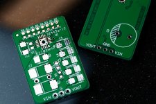
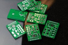
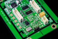
TPS7A4700 low noise PSU PCB
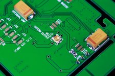
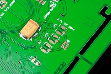
I got TPS7A4700 PCB last weekend. I assembled two of them tonight. One is MLCC version, the other is TAN version. I know there is piezoelectric effect connected to MLCC capacitors which can introduce mechanical vibration into noise. But I’m not quite sure by how much it will affect the power supply of an oscillator. Is there anybody has experience on this issue?
TPS7A4700 is a jumper programmable bipolar RF regulator. It can be easily set into 3.3V, 5V and etc with steps each 0.1V. Max input range goes to 36V. 4.17 μVRMS (10 Hz, 100 kHz) output noise level makes it industrial best so far. Another good thing is the max output current goes up to 1A. This feature makes it very suitable for powering Si570 which needs a very low noise power supply running at 100mA level.
One of the PCB caught fire during test because the TAN caps were reversing assembled by mistake. Whole board became black. I threw it into garbage bin and re-assemble a new one. So, please always be aware of TAN caps. Sometimes they are dangers. Never reverse of over voltage.
After that, both of them ran right away. Without load, one outputs 3.321V and the other 3.331V. It seems I can start testing the Si570 clock board now.
Ian
Attachments
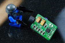
That looks like a lot of fun there Ian! Seems you needed the Lego fire department earlier though
A question that has just struck me is ... with that VQFN package, where is the index marking? How do you know which way it should sit on the pcb?!
Thermal pad has a cut corner so it's not difficult to indicate pin 1
. Ian
I got TPS7A4700 PCB last weekend. I assembled two of them tonight. One is MLCC version, the other is TAN version. I know there is piezoelectric effect connected to MLCC capacitors which can introduce mechanical vibration into noise. But I’m not quite sure by how much it will affect the power supply of an oscillator. Is there anybody has experience on this issue?
TPS7A4700 is a jumper programmable bipolar RF regulator. It can be easily set into 3.3V, 5V and etc with steps each 0.1V. Max input range goes to 36V. 4.17 μVRMS (10 Hz, 100 kHz) output noise level makes it industrial best so far. Another good thing is the max output current goes up to 1A. This feature makes it very suitable for powering Si570 which needs a very low noise power supply running at 100mA level.
One of the PCB caught fire during test because the TAN caps were reversing assembled by mistake. Whole board became black. I threw it into garbage bin and re-assemble a new one. So, please always be aware of TAN caps. Sometimes they are dangers. Never reverse of over voltage.
After that, both of them ran right away. Without load, one outputs 3.321V and the other 3.331V. It seems I can start testing the Si570 clock board now.
Ian
Beautiful!
I dont think the piezo effect is anything to worry about, otherwise why would they be used internally in the chrystek clock under the can? I prefer the panasonic special polymer for bulk decoupling though. at these low voltages you may find a large enough DC link polymer, which acts like a small battery
Si570 interest list:
1. bigpandahk
2. tagheuer
3. hochopeper
4. qusp (of course)
5. AR2 - definitely!
6. wktk_smile
7. hirez69
8. CeeVee - you bet!
9. number9
10. analog_sa - GB maniac
11. edbk
12. atom6422
13. misterrogers - Of Course!
14. NicMac - as usual!
15. Zoran 16. PET-240
17. Coolhead
18. Slartibartfasst
19. SYklab
20. Regland
21. Neb001
22. SPWONG
23. Greg Stewart (also of course!)
24. Vitalica
25. spm
26. Fridrik
27. ccliu
28. makumba1966
29. lindamar
30. Finaxe
31. Odysseas x2
32. palmito
33. crazikid
Updated me request for one extra board.
Si570 clock board V2.0 is running
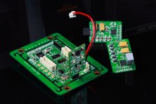
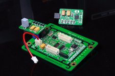
I start testing the Si570 V2.0 board today.
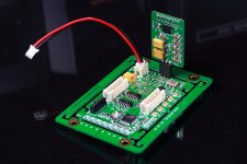
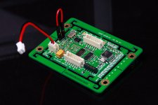
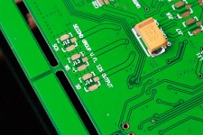
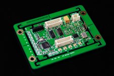
Now, it can generate eight audio frequencies for different application: 98.xxx, 90.xxx, 49.xxx, 45.xxx, 24.xxx, 22.xxx, 12.xxx, 11.xxx. U.fl footprints of additional group of I2S output placed at back of the PCB especially for dual mono configuration. As well as a pair of MCLK output sockets on top. An optional un-terminated MCLK output u.fl socket footprint placed at back. The un-terminated MCLK signal is expected has short raising time and less delay, but has to use very short cable. Three u.fl footprints for I2S input left on the back of the PCB. Optional customized decoupling cap foot prints left at back of PCB too.
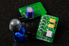
Because of the special requirement on power supply, from PCB V2.0 of Si570 clock board, a three pin external reg socket has been included on PCB for customized low noise power supply. Because of this, I even didn't mount the onboard LDO, I don't think ADP151 could still keep low noise performance at output current more than 100mA.
There are two options for powering the Si570 clock board. One option is using an external low noise reg such as TPS7A4700. The other option is using a LiFePO4 battery cell directly.
For the first option, I use the TPS7A4700 reg board which I built yesterday. Just simply plug it into the three pin socket of the si570 pcb. Any kind of 4-6.5V DC input works for it. However battery based DC input still preferred. I use 6V battery pack for today’s test (battery management board required of cause). Third party regs also work for this option, such as Salas shunt reg, TP trident and etc. But I did try any of them yet.
For the second option, you need short the input and output pin of the reg socket by a jumper and powering the DC input from a LiFePO4 battery cell, battery management board is a must in this case.
I run the si570 board at 90.xxx and 98.xxx MHz MCLK with ESS9018 working at sync mode, it sounds wonderful without any suspect.
The interesting thing I’ve noticed is that MLCC version and TAN version of TPS7A4700 sounds different. The MLCC version sound more close to the LiFePO4 battery cell. I need more time to look into this issue.
I use 74PO74 GHZ flip-flop for re-clocking the I2S at beginning. But glt mentioned that ESS9081 I2S SCK need a bit more delay to the MCLK to get better sound, so later on I will try different flip-flops with longer delay.
Please find the file names of the pictures below for more details.
Ian
I start testing the Si570 V2.0 board today.
Now, it can generate eight audio frequencies for different application: 98.xxx, 90.xxx, 49.xxx, 45.xxx, 24.xxx, 22.xxx, 12.xxx, 11.xxx. U.fl footprints of additional group of I2S output placed at back of the PCB especially for dual mono configuration. As well as a pair of MCLK output sockets on top. An optional un-terminated MCLK output u.fl socket footprint placed at back. The un-terminated MCLK signal is expected has short raising time and less delay, but has to use very short cable. Three u.fl footprints for I2S input left on the back of the PCB. Optional customized decoupling cap foot prints left at back of PCB too.
Because of the special requirement on power supply, from PCB V2.0 of Si570 clock board, a three pin external reg socket has been included on PCB for customized low noise power supply. Because of this, I even didn't mount the onboard LDO, I don't think ADP151 could still keep low noise performance at output current more than 100mA.
There are two options for powering the Si570 clock board. One option is using an external low noise reg such as TPS7A4700. The other option is using a LiFePO4 battery cell directly.
For the first option, I use the TPS7A4700 reg board which I built yesterday. Just simply plug it into the three pin socket of the si570 pcb. Any kind of 4-6.5V DC input works for it. However battery based DC input still preferred. I use 6V battery pack for today’s test (battery management board required of cause). Third party regs also work for this option, such as Salas shunt reg, TP trident and etc. But I did try any of them yet.
For the second option, you need short the input and output pin of the reg socket by a jumper and powering the DC input from a LiFePO4 battery cell, battery management board is a must in this case.
I run the si570 board at 90.xxx and 98.xxx MHz MCLK with ESS9018 working at sync mode, it sounds wonderful without any suspect.
The interesting thing I’ve noticed is that MLCC version and TAN version of TPS7A4700 sounds different. The MLCC version sound more close to the LiFePO4 battery cell. I need more time to look into this issue.
I use 74PO74 GHZ flip-flop for re-clocking the I2S at beginning. But glt mentioned that ESS9081 I2S SCK need a bit more delay to the MCLK to get better sound, so later on I will try different flip-flops with longer delay.
Please find the file names of the pictures below for more details.
Ian
Attachments
-
 UnterminalMCLK.JPG298.1 KB · Views: 267
 -
 I2Su.flInput.JPG330.1 KB · Views: 285
 -
 ThirdPartyREG.JPG275.9 KB · Views: 322
 -
 TPS7A47RegTAN.JPG334.7 KB · Views: 532
 -
 TPS7A47RegMLCC.JPG312.9 KB · Views: 536
 -
 BatteryPowerConfiguration.JPG292.2 KB · Views: 526
 -
 I2SforDualMONO.JPG323.8 KB · Views: 531
 -
 Si570ClockBoardV2.0.JPG304.6 KB · Views: 680
 -
 TwoMCLKoutput.JPG380.8 KB · Views: 300
looking great Ian! interesting point about BCK, can you not delay it with DSP? ie an alternate firmware, or jumper?
It's not just any delay though, so I think Ian is using some creative license there
We need the 'delay' to create a falling edge instead of rising edge in synch with the other signals.See:
it optimized to signals synchronized with the falling edge of the MCLK.
Unfortunately the CMOS version of Si570 doesn't have a inverted output. However it could still be achieved by replace the potato 74G74 with 74AC74 to get same amount of timing relationship for the 98.xxx and 95.xxx MCLK. Will give a try to see if there is any audible difference.
Note that this change might only work for those two clock frequencies and would probably need work to get the same relationship at 45/49MHz or any other pair of MCLK freq. Though the 'ES9018 brigade' probably aren't planning on using less than the 95/98MHz frequencies, were you? Acko wrote something a few weeks ago about trying this inverted mclk in his setup didn't he?
ahh yes i'm aware of the inverted trick, I just mistook him for talking of something else I hadnt heard of. I think I may have been the one that asked for it =) I think glt also mentioned it later in the thread so I didnt have to get the poking stick out...also mentioned it to Acko, aaah my brilliant minions go brainiacs go!! lol joking, its just nice to have someone so skilled that has the same goals!
yeah i'll be using 95/98
but I still wonder why the inversion couldnt be done internally before it even goes to the clock board? I thought cmos was symmetrical so an inverted signal could still be sent from the same part as the non inverted signal?
go brainiacs go!! lol joking, its just nice to have someone so skilled that has the same goals!yeah i'll be using 95/98
but I still wonder why the inversion couldnt be done internally before it even goes to the clock board? I thought cmos was symmetrical so an inverted signal could still be sent from the same part as the non inverted signal?
Last edited:
Si570 interest list.
Si570 interest list:
1. bigpandahk
2. tagheuer
3. hochopeper
4. qusp (of course)
5. AR2 - definitely!
6. wktk_smile
7. hirez69
8. CeeVee - you bet!
9. number9
10. analog_sa - GB maniac
11. edbk
12. atom6422
13. misterrogers - Of Course!
14. NicMac - as usual!
15. Zoran 16. PET-240
17. Coolhead
18. Slartibartfasst
19. SYklab
20. Regland
21. Neb001
22. SPWONG
23. Greg Stewart (also of course!)
24. Vitalica
25. spm
26. Fridrik
27. ccliu
28. makumba1966
29. lindamar
30. Finaxe
31. Odysseas x2
32. palmito
33. crazikid
34. deanoUK
Cheers.
Si570 interest list:
1. bigpandahk
2. tagheuer
3. hochopeper
4. qusp (of course)
5. AR2 - definitely!
6. wktk_smile
7. hirez69
8. CeeVee - you bet!
9. number9
10. analog_sa - GB maniac
11. edbk
12. atom6422
13. misterrogers - Of Course!
14. NicMac - as usual!
15. Zoran 16. PET-240
17. Coolhead
18. Slartibartfasst
19. SYklab
20. Regland
21. Neb001
22. SPWONG
23. Greg Stewart (also of course!)
24. Vitalica
25. spm
26. Fridrik
27. ccliu
28. makumba1966
29. lindamar
30. Finaxe
31. Odysseas x2
32. palmito
33. crazikid
34. deanoUK
35. Julf
wheres your 'of course' deanoUK? you dont show a great deal of commitment...
hehe
When yow cum from brumingon cheers says it all. he he.
- Home
- Source & Line
- Digital Line Level
- Asynchronous I2S FIFO project, an ultimate weapon to fight the jitter