Hi BigpandaHK,I am using the same charger as yours but i believe your battery should be LiMH not LiFEPO4.
¡ïʨ×ÓÕýÆ·¡ï¸ß¶Ë LION 7.4V 5200MAH 30C ¾ÛºÏÎï﮵ç³ØBG712-ÌÔ±¦Íø
According to the translation, it is supposed to be Lithium Polymer, their brand is Lion.
was a good suggestion mate!
I want to know what bigpandahk has planned now he's the only guy apart from Ian with more than one of those isol boards!
As I may not require the second isolator board at this stage, I can send it to you then we have one ore tester.
not at those charge voltages it isnt LiFePO4, anyway yes Lipo are ok, bit noisy and many packs have switchmode limiting circuit
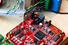
THat's the reason not buying this kind of battery pad. This is what I am using :
18650 LiFepO4 1800mAh 3.2V
Attachments

As I may not require the second isolator board at this stage, I can send it to you then we have one ore tester.
Well, that really is a hard offer to knock back. I would like to hear Ian's thoughts though, it's his to allocate as he wishes IMO.
I don't have a FIFO to use it with yet unfortunately so that is why I'd held out of the testing.
Well, that really is a hard offer to knock back. I would like to hear Ian's thoughts though, it's his to allocate as he wishes IMO.
I don't have a FIFO to use it with yet unfortunately so that is why I'd held out of the testing.
You are right, I should have Ian's consent before making such offer.
Hi guys, I don't have any problem. Go ahead whatever you think it's good.
Ian
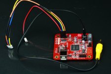
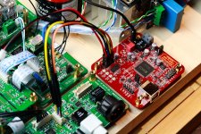
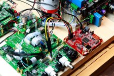
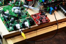
Hook up XMOS WaveIO USB interface to Ian FIFO KIT
I know a lot of people did this configuration before. I just confirm it by myself once again.
There are three ways hoop up XMOS WaveIO USB interface to FIFO KIT, Please see the attached pictures for details:
1, Connecting the isolated I2S output into the I2S backdoor on the S/PDIF Interface Board. The configuration is highly recommended. But you need an additional Vdd for the isolator. You can feed it with the 5V power supply from J13 on the S/PDIF board.
2, Connecting the isolated S/PDIF output into COX input on the S/PDIF board by a 75ohm coaxial cable.
3, Connecting the isolated I2S output into the FIFO input directly. But please do not use this configuration unless you need only one source from XMOS interface. You can get the isolator power supply from J5 of the FIFO board for this case.
Please never use the un-isolated outputs of the XMOS. PC ground from USB is noisy and not safe enough.
The XMOS WaveIO USB interface sounds great on my system and works perfect with different kinds of player software. To connect it with the FIFO KIT is very easy as well. As a USB based I2S or S/PDIF source, it would be recommended.
Ian
Attachments
Ian,
A very interesting post! I am going with WaveIO as my only source at this stage. I was intrigued that you recommended using isolated i2s output between it and the FIFO, even with the isolator between FIFO and clock board. I have powered mine with a lt1085 reg (usb power and ground are connected but not powering anything). Anyway it seems logical to use the isolated output with the way you have written it. I had previously not pursued this option because I had thought FIFO was 3.3V i2s input only, now that you have reminded me that 5V i2s intput can work and FIFO 5V supply output is perfect for this it looks like a great option.
Computer PSU noise can stay on the XMOS side; FIFO fpga noise can stay on the FIFO; and a clean re-clocked low jitter output signal from the clock board. What more could we hope for?! I am pretty excited for the next GB to reach critical numbers!
Also, I know that you check the FIFO for bit-perfect throughput as part of the testing, is there any way to test the whole chain from transport to i2s output? I am not sure how the testing setup for that works so its just me thinking out loud there, though I am 99.999% sure there is not a problem at all.
Cheers,
Chris
Last edited:
Si570 interest list:
1. bigpandahk
2. tagheuer
3. hochopeper
4. qusp (of course)
5. AR2 - definitely!
6. wktk_smile
7. hirez69
8. CeeVee - you bet!
9. number9
10. analog_sa - GB maniac
11. edbk
12. atom6422
13. misterrogers - Of Course!
14. NicMac - as usual!
15. Zoran
16. PET-240
17. Coolhead
18. Slartibartfasst
19. SYklab
20. Regland
21. Neb001
22. SPWONG
23. Greg Stewart (also of course!)
24. Vitalica
25. spm
Ian,
A very interesting post! I am going with WaveIO as my only source at this stage. I was intrigued that you recommended using isolated i2s output between it and the FIFO, even with the isolator between FIFO and clock board. I have powered mine with a lt1085 reg (usb power and ground are connected but not powering anything). Anyway it seems logical to use the isolated output with the way you have written it. I had previously not pursued this option because I had thought FIFO was 3.3V i2s input only, now that you have reminded me that 5V i2s intput can work and FIFO 5V supply output is perfect for this it looks like a great option.
Computer PSU noise can stay on the XMOS side; FIFO fpga noise can stay on the FIFO; and a clean re-clocked low jitter output signal from the clock board. What more could we hope for?! I am pretty excited for the next GB to reach critical numbers!
Also, I know that you check the FIFO for bit-perfect throughput as part of the testing, is there any way to test the whole chain from transport to i2s output? I am not sure how the testing setup for that works so its just me thinking out loud there, though I am 99.999% sure there is not a problem at all.
Cheers,
Chris
Yes,the I2S input on my FIFO board was designed 5V toleranced
") . So, just go ahead with 5V logic don't worry about the logic level problem.
. So, just go ahead with 5V logic don't worry about the logic level problem.Loop testing was done by another FPGA based board. Basically there integrated an I2S data generator and an I2S receiver/tester inside. It has both 24bit and 32bit mode. By comparing the input and output bit by bit, the bit perfect test will be achieved.
So, it doesn't matter how 'big' the loop is. I tested bit perfect with loop: I2S - FIFO board - Isolator board - Clock board - S/PDIF interface board (output) - OPT/COX cable - S/PDIF interface board (input) - I2S , is that loop big enough
. I might have some psychological problem
, I always need the bit-perfect test before any listening test.Ian
Ian
Is there any way to connect the WaveIO to the TTL input of SPDIF?
I do not suggest connecting WaveIO to TTL S/PDIF input on spdif board, because it's not a isolated signal and very dangerous to your system.
Ian
Yes,the I2S input on my FIFO board was designed 5V toleranced
Loop testing was done by another FPGA based board. Basically there integrated an I2S data generator and an I2S receiver/tester inside. It has both 24bit and 32bit mode. By comparing the input and output bit by bit, the bit perfect test will be achieved.
So, it doesn't matter how 'big' the loop is. I tested bit perfect with loop: I2S - FIFO board - Isolator board - Clock board - S/PDIF interface board (output) - OPT/COX cable - S/PDIF interface board (input) - I2S , is that loop big enough
I might have some psychological problem
Ian
Excellent!
So the only thing not possible to evaluate in that topology is computer->spdif via the waveio; OR computer -> i2s via waveio. Or any other issues with other transports for that matter.
Can you see now that you might not be alone in the psychological problem stakes
Excellent!
So the only thing not possible to evaluate in that topology is computer->spdif via the waveio; OR computer -> i2s via waveio. Or any other issues with other transports for that matter.
Can you see now that you might not be alone in the psychological problem stakes
Did you try playing a DTS file? If DST light is on, mostly,the bit-perfect is approved. But it only apply to s/pdif.
Cheers,
Ian
Addressing the video synch issues
As the next GB gets closer, the video synch issue has been getting closer to the top of my priority list of things I should look into addressing for my application of Ian's FIFO since my only source is a computer and I do occasionally watch videos through it.
I have been thinking about methods to address the video synch problems caused by the FIFO delay. I can see that it is really only feasible to address this issue for computer based video playback, I see no way to transparently address the problem on a proprietary video playing device or television.
So keep in mind any solution that i might propose will be within those constraints.
As a starting point, before I make any useless suggestions, could those of you with FIFO's already help me clarify my understanding of the issue(s).
Considering a constant stream of audio, no breaks as may be possible in music playback. The FIFO buffers when audio stream starts until the memory is 1/2 full. This delay time is dependant on the fs, for obvious reasons. Then depending on the long term differences between transport clock and output clock, the FIFO will either accumulate more samples, or slowly eat into its store of extra samples. With a FIFO half full delay of D we will either end up with a delay approaching 0 or a delay approaching 2*D, over a bit more than 24mins at the soonest for 44.1kHz media, if the difference in clock speeds is less, the this period of time may be longer. (I found the 24mins figure very early in the thread, not sure if Ian's improved things since then but when doing a search tonight I didn't find anything)
Is that roughly the sequence of events?
We do not have any rate feedback because there is nothing that exists (yet) that could be interfaced to.
So the problem to solve that I can think of now are:
1. Video files may be accompanied with a variety of audiofiles with different sample-rates and consequently different FIFO delays.
2. Video files may, depending on software player used, either synch to a video or audio clock as these will be handled separately in most, reasonable, software packages. This will typically still cause some drift in timing between video and audio during a normal video file playback. There is only a few pieces of software that I know of that do this well and keep this drift as small as possible, the FIFO will circumvent any of those typical methods though, unless we get clever.
3. Video files may have a variety of video frame rates (23.996, 24, 30, 50, 60Hz are all 'common').
5. Depending on the refresh rate of the screen, the software will have to either force the screen refresh rate to change (this will typically only happen in a HTPC environment, so not common FIFO application); OR it will have to 'resample' the video frames to suit the screen refresh rate. This resampling causes the video equivalent of jitter, usually called judder.
That is all of the issues I can think of that are what is observed when dealing with video and audio synchronisation.
So what we need is a method that initially delays each video played by the 'FIFO half full time' listed in Ian's documentation. We then need to determine if the buffer size is growing/diminishing and at what rate; OR we need to keep the drift to a minimum and ideally, less than an acceptable threshold.
I have 2 untested ideas on how to address the first sentence, but none on how to address the second as yet.
Reducing the initial FIFO buffer delay will not reduce any of the issues other than #1. in my list above, and still, it will not solve it; it will mean that the FIFO may potentially under-run sooner.
Cheers,
Chris
how quickly can the buffer be emptied? Ian? is there a possibility it could ever be done between clock ticks as a matter of urgency if it came to that?
nice post Chris!
take your washroom break before the buffer fills!
As the next GB gets closer, the video synch issue has been getting closer to the top of my priority list of things I should look into addressing for my application of Ian's FIFO since my only source is a computer and I do occasionally watch videos through it.
I have been thinking about methods to address the video synch problems caused by the FIFO delay. I can see that it is really only feasible to address this issue for computer based video playback, I see no way to transparently address the problem on a proprietary video playing device or television.
So keep in mind any solution that i might propose will be within those constraints.
As a starting point, before I make any useless suggestions, could those of you with FIFO's already help me clarify my understanding of the issue(s).
Considering a constant stream of audio, no breaks as may be possible in music playback. The FIFO buffers when audio stream starts until the memory is 1/2 full. This delay time is dependant on the fs, for obvious reasons. Then depending on the long term differences between transport clock and output clock, the FIFO will either accumulate more samples, or slowly eat into its store of extra samples. With a FIFO half full delay of D we will either end up with a delay approaching 0 or a delay approaching 2*D, over a bit more than 24mins at the soonest for 44.1kHz media, if the difference in clock speeds is less, the this period of time may be longer. (I found the 24mins figure very early in the thread, not sure if Ian's improved things since then but when doing a search tonight I didn't find anything)
Is that roughly the sequence of events?
We do not have any rate feedback because there is nothing that exists (yet) that could be interfaced to.
So the problem to solve that I can think of now are:
1. Video files may be accompanied with a variety of audiofiles with different sample-rates and consequently different FIFO delays.
2. Video files may, depending on software player used, either synch to a video or audio clock as these will be handled separately in most, reasonable, software packages. This will typically still cause some drift in timing between video and audio during a normal video file playback. There is only a few pieces of software that I know of that do this well and keep this drift as small as possible, the FIFO will circumvent any of those typical methods though, unless we get clever.
3. Video files may have a variety of video frame rates (23.996, 24, 30, 50, 60Hz are all 'common').
5. Depending on the refresh rate of the screen, the software will have to either force the screen refresh rate to change (this will typically only happen in a HTPC environment, so not common FIFO application); OR it will have to 'resample' the video frames to suit the screen refresh rate. This resampling causes the video equivalent of jitter, usually called judder.
That is all of the issues I can think of that are what is observed when dealing with video and audio synchronisation.
So what we need is a method that initially delays each video played by the 'FIFO half full time' listed in Ian's documentation. We then need to determine if the buffer size is growing/diminishing and at what rate; OR we need to keep the drift to a minimum and ideally, less than an acceptable threshold.
I have 2 untested ideas on how to address the first sentence, but none on how to address the second as yet.
Reducing the initial FIFO buffer delay will not reduce any of the issues other than #1. in my list above, and still, it will not solve it; it will mean that the FIFO may potentially under-run sooner.
Cheers,
Chris
Good idea Chris.
I heard some softare based players have audio/video delay function, they call it as lips sync. As well as some blueray player. I also found some video dealy controller on ebay. I'm not sure which one works with FIFO. But it worth to give a try.
I'm an audiophile, so the FIFO was designed optimized to audio. That's why I use big buffer memory rather than a smaller one.
Of cause reducing the FIFO size will shorten the dealy time, but it will leave less space for the smart FIFO control stratagy hence degrade the SQ due to frequently overflow/empty, eapecially for playing long audio track, which is what I'm not tending to.
But just as you mentioned, there still some possibles solutions, what I could think of are:
1, Enable the audio/video delay control function on the video player.
2, Trying to up-sampling the audio stream into higher Fs, for example, 196Khz only has 1/4 delay of 48Khz, says around just 150ms.
3, Hardware based delay controler placed between player and HDTV.
Sandy is comming now
. Ian
- Home
- Source & Line
- Digital Line Level
- Asynchronous I2S FIFO project, an ultimate weapon to fight the jitter