Hello,
I hope the people who had trouble with that board can answer that question. If there are several people having similar problems with the same boards it would be better if the complete production run will be replaced. I guess the production run is not 1000 pieces. So if there were 200 in that serie. So many issues in this reduced amount of time is not a good sign.
I think i will go for the mounted and tested stack and send the parts i have already in stock back yo be used for the " stack"
Greetings, Eduard
Hi SimonIan updated the manual once I told him by recommending Lower AC output voltage. The issue was ucpure stopped charging and only way I saw this problem
Did you use 9v AC at the UcPure input? Did you experience that error with 12v AC?
The drop down voltage would of couse be lower and therefore lower heat at the board with a 9v AC input. But even after rectification of a 12 v AC input we should be home safe when the board also accept a directly 18-20v DC input.
Thanks
Regards Mikkel
Hello!
Question to respected forum participants. I want to use Fifopi Q2 for an upgraded DAC. I don't plan to use ReceiverPi or Raspberry. In this case, FifoPi will receive i2s from the Spdif converter on the CS8412. Will this design work? Or is it necessary to use the newer Fifopi Q3 or Q7,
How to properly supply power to Fifopi Q2 in this case. 5V is enough for terminals J3 and J5. Or you also need 3.3V on gpio J1 (pins 1 and 17).
I think more like self ignition dynamite🧨 ‼️These supercaps being available to anyone is really like dropping a pile of loaded shotguns in kindergarten playground.
Thanks Simon.Hi Mikkel,
Yes I dropped from a 12v to 9v and all is working well now after Ian advice.
How many amp. or VA is you 9v transformer rated at!🙂
Hello,
I hope the people who had trouble with that board can answer that question. If there are several people having similar problems with the same boards it would be better if the complete production run will be replaced. I guess the production run is not 1000 pieces. So if there were 200 in that serie. So many issues in this reduced amount of time is not a good sign.
I think i will go for the mounted and tested stack and send the parts i have already in stock back yo be used for the " stack"
Greetings, Eduard
I am also having a problem with Station Pi Pro MKII. When I stack all the modules in a single stack everything works as expected. With Station Pi Pro, the data(SD) is lost somewhere between the RPi / Station Pi Pro daughter board and the other side of Station Pi Pro and the Monitor Pi always shows MUTE. As per Ian, when SD is zero, Monitor Pi will show MUTE.
Has anyone had this problem and solved it? I tried to look for a dry solder and reflowed all the SD pins on all connectors.
Regards, Subbu.
Hi Subbu K,
I seem to have experienced a very similar problem to yours. With the help of Ian Canada and of my friend, @Chris1967, I was able to determine that the problem was indeed the StationPi Pro MkII. Unfortunately, I did not have a Monitor Pi Pro to support the investigation. Now, I have ordered one and am waiting for it (probably tomorrow).
I cannot say whether the PCB batch has been faulty or not, but Ian was quick to lend a helping hand and replace my StationPi Pro.
Hello,
Spewing out update after update might not be the right way.
Better have the percentage of people who can succeed in building their own digital " stack " without issues is far more important.
I still have the first stationpi board so i guess that is not causing my problem.
If i am right you can build a digital system with raspberry in a seperated enclosure connected with hdmi and no stationpi board at all.
If there is a tiny quality issue a little bit of " rough handling" could already cause a board not to work partially . After all there is a pile of boards with standoffs that could be over tighten creating to much force upon the boards on a 24/7 basis. Even a tiny standoff can execute considerable force and kind of " twist" a board a bit
Greetings,Eduard
My guess, based on the schematic published, it should most likely be a dry solder joint type of issue. One more thing I am about to try is to reflow all the pins (at least the ones that are needed for I2S) on all connectors. If that doesn't work will send the board to Ian for further investigation.
I moved from Station Pi to Pro to add more sources using Receiver Pi Pro. With Station Pi no issues and was running fine past 1+ years.
Regards, Subbu.
I moved from Station Pi to Pro to add more sources using Receiver Pi Pro. With Station Pi no issues and was running fine past 1+ years.
Regards, Subbu.
Last edited:
Thank you for taking a look!What an impressive job. Thank you for sharing.
Sounds like a plan. Needless to say, you can check the continuity of every path with a multimeter. BeepMy guess, based on the schematic published, it should most likely be a dry solder joint type of issue. One more thing I am about to try is to reflow all the pins (at least the ones that are needed for I2S) on all connectors. If that doesn't work will send the board to Ian for further investigation.
I moved from Station Pi to Pro to add more sources using Receiver Pi Pro. With Station Pi no issues and was running fine past 1+ years.
Regards, Subbu.
")
Hello,
A few weeks ago there was a member with a connector " coming off ' from the board. It looked liked a serious connector that once probably soldered could break the board in two. So maybe this one had some cold joints too?
If i am right a cold solderjoint should be desoldered cleaned and soldered again using fresh solder. Probably the connectors have rather big soldering spots so not to difficult.
What about the other parts are there no cold joints on these areas?
This is the only board with this issue?
Would be weird to have some boards in your stacks with barely good enough joints on some spots and spend a small fortune on clocks.
Greetings Eduard
I had a tough time reflowing the pins of the 40-pin socket (J1) on the Raspberry Pi side of the Station Pi Pro. I had to use a lot of flux to make the new solder even stick. Finally, the Station Pi Pro works now. I no longer see the MUTE on MonitorPi Pro instead it shows Play and displays the SD frequency.
Anyone having issues first look at solder joints on J1. I have reflowed the I2S pins on all the sockets and pin headers so that no dry solder shows up at a later point.
What should have been a plug-and-play solution took one whole weekend
Regards,
Subbu
Anyone having issues first look at solder joints on J1. I have reflowed the I2S pins on all the sockets and pin headers so that no dry solder shows up at a later point.
What should have been a plug-and-play solution took one whole weekend
Regards,
Subbu
Doesn't it work with any DAC, or just not with the new one ? Are you using the same HDMI cable ?Hi,
No music…
I had to disconnect my DDC for a few weeks because I am reviewing a DAC. I tried to plus it back last week-end and I have no sound.
The clocks seem to work. I see see both frequencies playing. However, I see dashes on MonitorPi when I play DSD files.
It is connected with i2s using a hdmi cable on a Holo May KTE. PLL is set to Off. It displays UNLOCK on the May and it stays there. This is weird…
i’ll try to use another hdmi cable. I’ll check again if all the connections are solid. I don’t know where to look.
Any hints?
Thank you,
Yves
Hello,
The old solder containing some lead was easier to work with so if both your solder and the one present on the board are the new one there will be more people wasting time on this problem.
The last time i used flux was during " handicraft education" at the age of 12. After using flux it needs to be removed completely so i will always used old fashion solder
You don't want the problem to pop up again.
Don't tell us this is part of diy because it is not especially for the ones with a limited toolbox and experience.
Ian better just send a replacement to the people having doubts too and spend time on quality control.
Greetings, Eduard
9v at 5A is what i am using.Thanks Simon.
How many amp. or VA is you 9v transformer rated at!🙂
For my 15v UCPure 12v works perfectly fine as well, I was using 15v and made the change
Congratulations on the successful effort. Furthermore, that's a very interesting outcome. I've also suspected some dry joints with my non-functioning StationPi Pro, but I did not try to reflow it, but sent it to Ian directly, so that he can have a look at it and determine the problem.I had a tough time reflowing the pins of the 40-pin socket (J1) on the Raspberry Pi side of the Station Pi Pro. I had to use a lot of flux to make the new solder even stick. Finally, the Station Pi Pro works now. I no longer see the MUTE on MonitorPi Pro instead it shows Play and displays the SD frequency.
Anyone having issues first look at solder joints on J1. I have reflowed the I2S pins on all the sockets and pin headers so that no dry solder shows up at a later point.
What should have been a plug-and-play solution took one whole weekend
Regards,
subbeau
Anyways, thanks for the update. I hope that you are rewarded by the sound improvement.
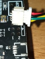
Hello,
This happened to a member on another board.
I dont know if this connector has a kind of locking mechanism. Even if it doesnt it would be strange that the lock would be strong enough to pull the receiving part of the connector off the board. It looks like the pins are still there.
Could this be a cold solder joints as well. I mean there are six joints those would give a strong bond
.Greetings,Eduard
Attachments
FWIW I use flux on everything. It makes soldering easy and quick and results in a great joint. If it is on a PCB, then it must be cleaned. Rubbing alcohol and an old toothbrush will clean it up in a jiffy. If it is a point to point connection I don't bother to clean.
- Home
- Source & Line
- Digital Line Level
- Asynchronous I2S FIFO project, an ultimate weapon to fight the jitter